Casting nozzle
一种喷嘴、金属壳体的技术,应用在铸造设备、铸造熔融物容器、制造工具等方向,能够解决危险性升高、密合性降低、有间隙等问题,达到抑制或防止应力集中、制造工序简朴且容易、防止漏钢的效果
- Summary
- Abstract
- Description
- Claims
- Application Information
AI Technical Summary
Problems solved by technology
Method used
Image
Examples
no. 1 Embodiment approach
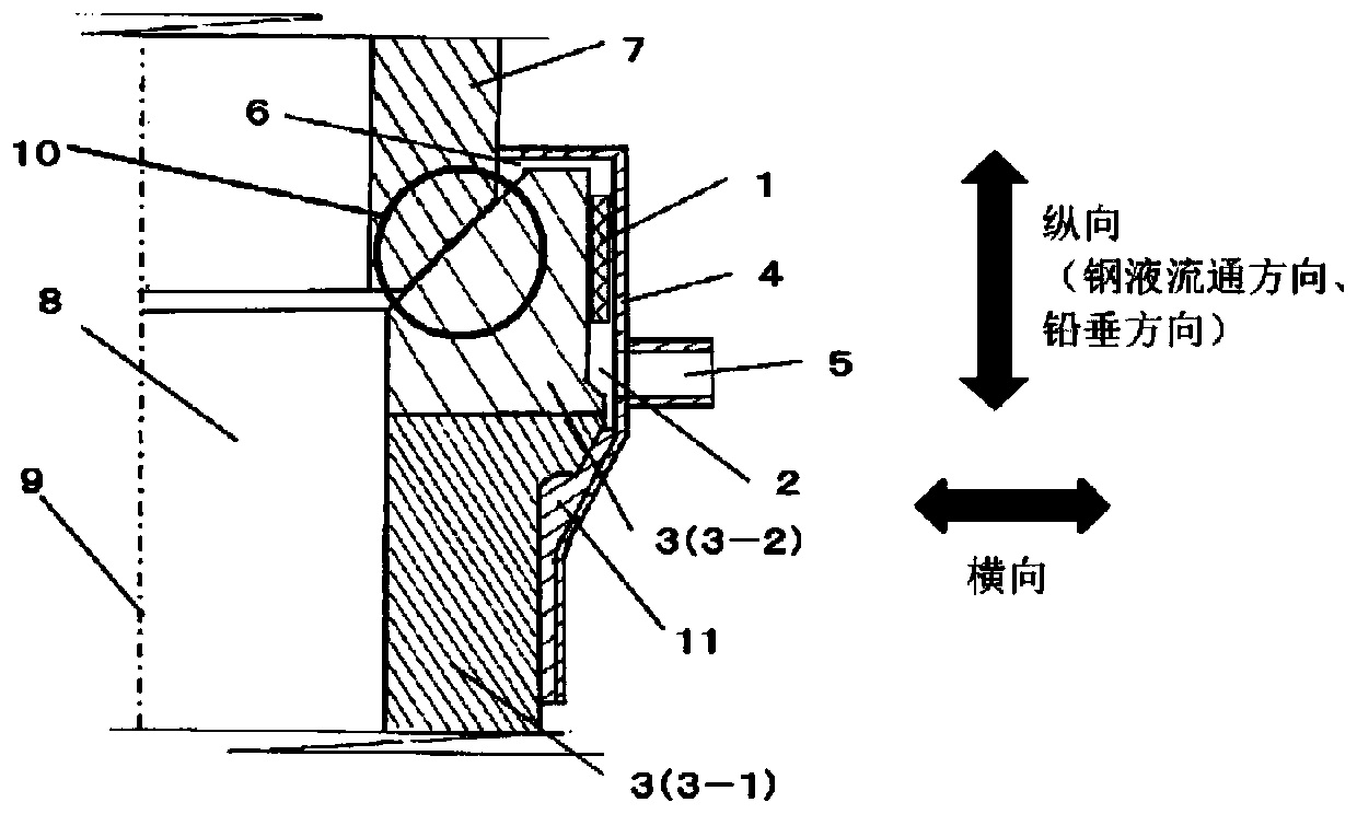
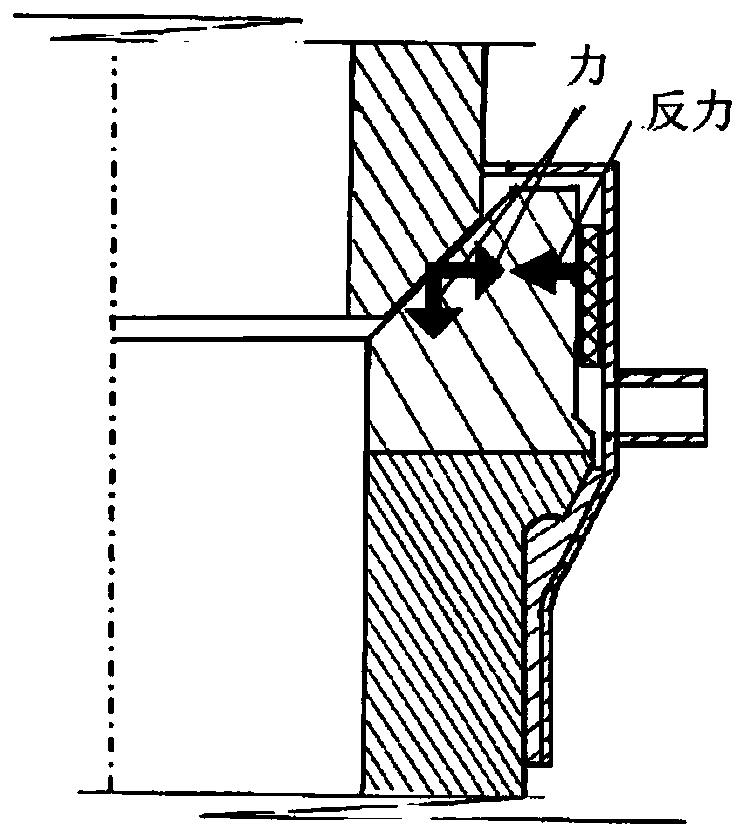
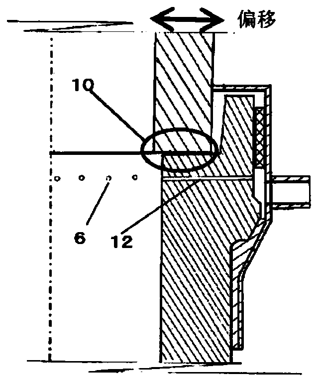
[0051] when referring to Figure 4 When the existing long nozzle shown is described, a gas pool is arranged between the outer peripheral surface of the long nozzle body 3 (in this specification, also only referred to as "the outer peripheral surface of the body") and the inner peripheral surface of the metal shell 4. 2 of the long nozzle body 3 (in this specification, also referred to simply as "body"), cracks and other damages are caused by the following situation, that is, at the junction with the lower nozzle 7, from the long nozzle In the flow direction of molten steel (vertical direction, hereinafter also referred to as "longitudinal"), the central axis exerts a force in the outer peripheral direction, that is, the radial direction (hereinafter also referred to as "transverse direction").
[0052] This force in the radial direction is mainly due to either (1) pressure contact at the junction of the lower nozzle and the long nozzle, or (2) local contact or local pressuriza...
Embodiment A
[0069] Example A is, in figure 1 In the structure, the bridging part is an iron round bar, and it is arranged to extend in the direction (longitudinal direction) parallel to the longitudinal direction (longitudinal direction) of the long nozzle by welding at 8 positions on the inner peripheral surface of the metal shell. .
[0070] In practice, in the existing structure without bridged parts (comparative example (from figure 1 In the structure (embodiment A) except the bridging part 1 structure)), there are longitudinal cracks on the long nozzle body and even damages separated from the cracks, but by providing the long nozzle of the present invention of embodiment A, As a result, there was no damage including cracks in the long nozzle body.
[0071] In addition, it is considered that in the case of the following lateral restraint and other structures having a higher lateral stress dispersion effect, the effect of suppressing or preventing damage such as cracks can be further...
no. 2 Embodiment approach
[0075] Such as Figure 12 As illustrated, in this embodiment, at least a part (a part or substantially the whole) of the gas cell 2 is filled with heat-resistant particles 1A, and the aforementioned bridging is formed by filling the heat-resistant particles 1A. Part 1 (the bridging part) of . Moreover, since the bridging portion 1 restricts the radial direction of the outer peripheral surface of the body 3 as described above, and at the same time, the heat-resistant particles 1A constituting the bridging portion 1 have the effect of dispersing stress, it is possible to suppress or prevent the nozzle body from 3 of the destruction.
[0076] In the present invention, it is preferable to fill (restrict) the heat-resistant particles 1A in the gas cell in a state where they are not bonded to each other and are in contact with any surface in the gas cell but are not bonded (bonded) (substantially overall area). That is, it is preferable that the heat-resistant particles 1A are re...
PUM
 Abstract
Description
Claims
Application Information
 - R&D
- Intellectual Property
- Life Sciences
- Materials
- Tech Scout
- Unparalleled Data Quality
- Higher Quality Content
- 60% Fewer Hallucinations
Browse by: Latest US Patents, China's latest patents, Technical Efficacy Thesaurus, Application Domain, Technology Topic, Popular Technical Reports.
© 2025 PatSnap. All rights reserved.Legal|Privacy policy|Modern Slavery Act Transparency Statement|Sitemap|About US| Contact US: help@patsnap.com


