Eureka AIR delivers breakthrough ideas for toughest innovation challenges, trusted by R&D personnel around the world.

Vehicle battery-carrying floor structure

a battery-carrying floor and vehicle technology, applied in the direction of battery/cell propulsion, vehicle sub-unit features, electric propulsion mounting, etc., can solve the problems of increasing and reducing the number of battery packs, and the structure has little flexibility in regard to the carrying capacity of battery packs

Active Publication Date: 2021-01-19
TOYOTA JIDOSHA KK
View PDF12 Cites 0 Cited by
  • Summary
  • Abstract
  • Description
  • Claims
  • Application Information

AI Technical Summary

Benefits of technology

[0094]According to the first aspect, flexibility with respect to the battery pack carrying capacity can be increased.
[0095]According to the second aspect, the strength and rigidity of the parts where the partition portions are formed can be enhanced.
[0096]According to the third aspect, damage to the reinforcement portions can be inhibited or prevented.
[0097]According to the fourth or sixth aspect, the bottom plate member can be made lighter in weight.
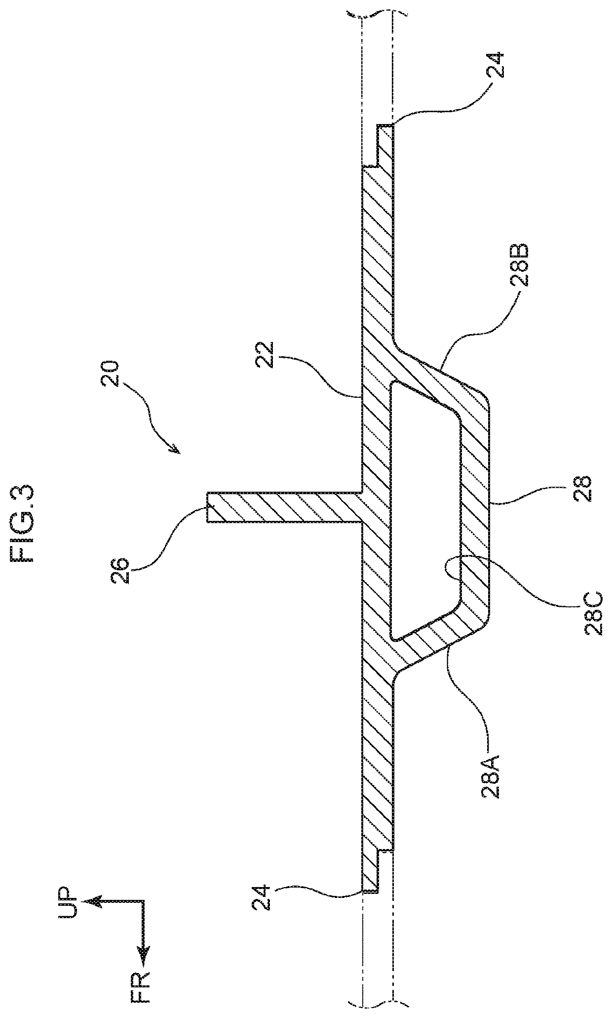
[0012]FIG. 5C is a side sectional view showing joint portions at upper surface sides and lower surface sides of the unit members of the vehicle battery-carrying floor structure pertaining to the embodiment;
[0015]FIG. 7 is a perspective view showing a first example modification of the vehicle battery-carrying floor structure pertaining to the embodiment;
[0100]According to the eighth aspect, the ingress of muddy water and / or rain water, for example, through the joint portions can be inhibited or prevented.

Problems solved by technology

However, in this kind of structure, the number of battery packs that the structure holds is undifferentiated, so increases and decreases in the number of battery packs cannot be accommodated.
In other words, this kind of structure has little flexibility with respect to the battery pack carrying capacity.

Method used


Image

  • Vehicle battery-carrying floor structure
  • Vehicle battery-carrying floor structure
  • Vehicle battery-carrying floor structure

Examples


Embodiment Construction

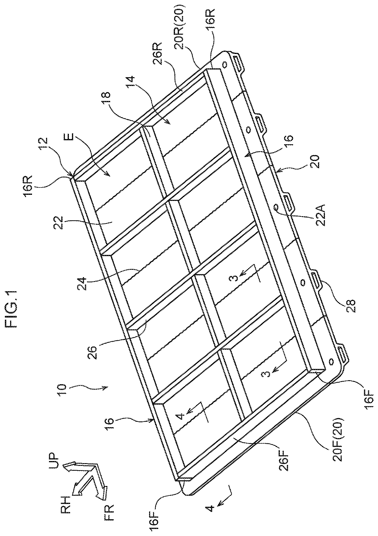
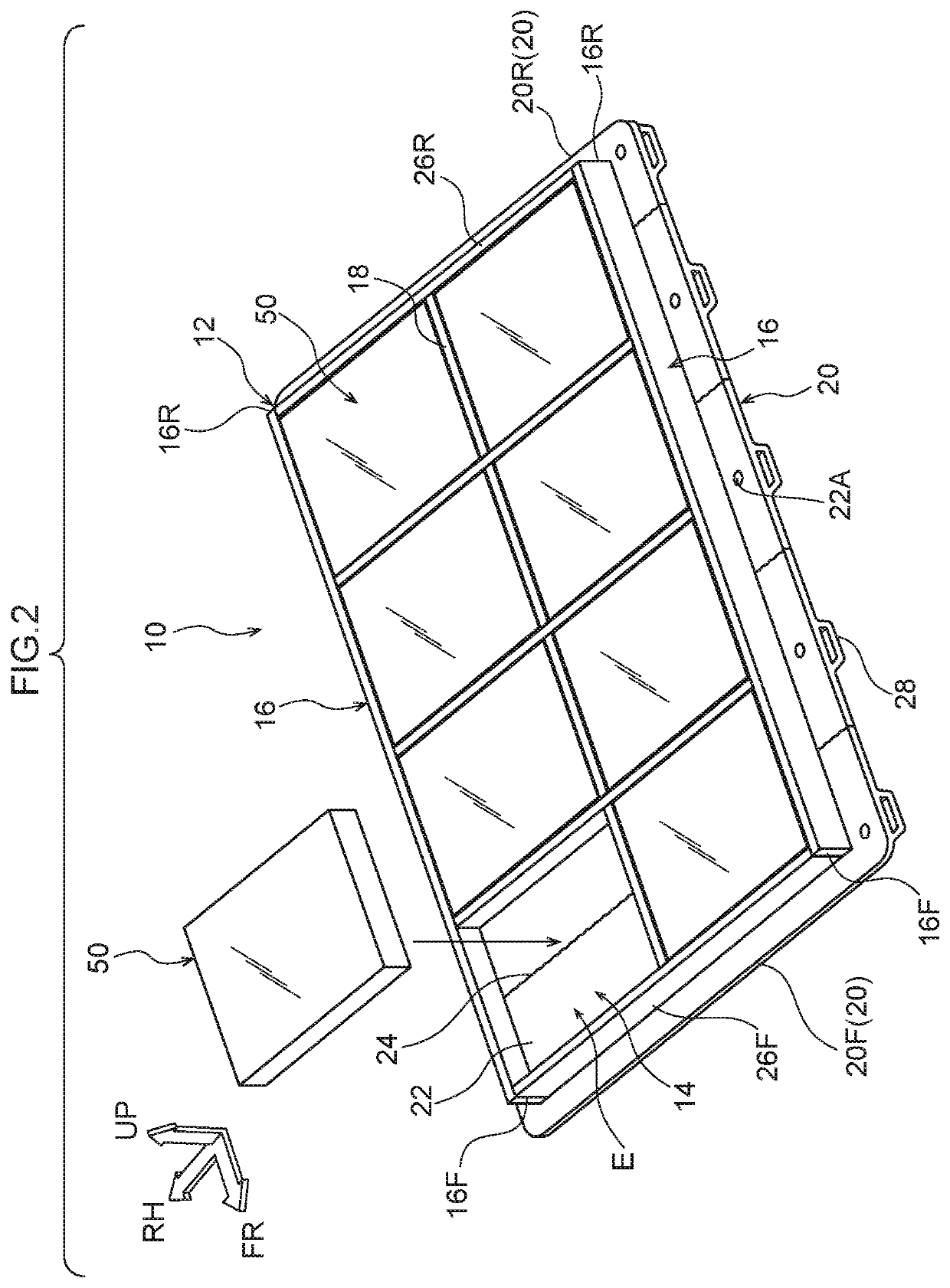
[0023]An embodiment pertaining to the disclosure will be described in detail below on the basis of the drawings. It will be noted that for convenience of description, arrow UP appropriately shown in the drawings indicates a vehicle body upward direction, arrow FR indicates a vehicle body forward direction, and arrow RH indicates a vehicle body rightward direction. Consequently, when in the following description the directions of upper / lower, front / rear, and right / left are used without further specification, these will be understood to mean upper / lower in the vehicle body upward and downward direction, front / rear in the vehicle body forward and rearward direction, and right / left in the vehicle body rightward and leftward direction (the vehicle width direction).

[0024]As shown in FIG. 1 and FIG. 2, a vehicle battery-carrying floor structure 10 pertaining to the embodiment is configured by a battery case 12 that holds plural battery packs 50. The battery case 12 is configured to include...


PUM


Abstract

A vehicle battery-carrying floor structure that includes: a bottom plate member that has a plurality of unit members that are arranged in a vehicle body forward and rearward direction and that are joined by joining opposing joint portions, each unit member having a flat plate portion that extends in a vehicle width direction and that has the joint portions formed at an end portion facing the vehicle body forward direction and at an end portion facing the vehicle body rear direction and a partition portion that is disposed upright so as to extend in the vehicle width direction on an upper surface of the plate portion; and side plate members that are provided on an upper surface of the bottom plate member on outer sides in the vehicle width direction of the partition portions and form, with the partition portions, regions that hold battery packs.

Description

CROSS-REFERENCE TO RELATED APPLICATION[0001]This application is based on and claims priority under 35 USC 119 from Japanese Patent Application No. 2018-139351 filed on Jul. 25, 2018, the disclosure of which is incorporated by reference herein.BACKGROUNDTechnical Field[0002]The present disclosure relates to a vehicle battery-carrying floor structure.Related Art[0003]A structure is known where side members are joined by welding to the top of a peripheral edge portion of a bottom plate and where plural cross members that extend in a vehicle width direction are joined by welding to, so as to be arranged side by side in a vehicle body forward and rearward direction on, the bottom plate, with battery packs being put between the cross members on the bottom plate (e.g., see Japanese Patent No. 5,372,128).[0004]However, in this kind of structure, the number of battery packs that the structure holds is undifferentiated, so increases and decreases in the number of battery packs cannot be accom...

Claims


Application Information

Patent Timeline
Patent Type & Authority Patents(United States)
IPC IPC(8): B60K1/04B60L50/60
CPCB60K1/04B60L50/66B60K2001/0438B62D25/20B60Y2410/124Y02T10/70
Inventor MATSUO, YASUHIDEKAGAMI, AYAKA
Owner TOYOTA JIDOSHA KK
Why Eureka
Eureka Blog
Learn More