
Vibration damper having adjustable damping valve

A technology of vibration damper and damping adjustment, which is applied in the direction of shock absorber, shock absorber, spring/shock absorber, etc., to achieve the effect of optimizing structural space utilization, high stability, and simple closed technology

Active Publication Date: 2020-12-22
ZF FIEDRICHSHAFEN AG
View PDF12 Cites 0 Cited by
  • Summary
  • Abstract
  • Description
  • Claims
  • Application Information

AI Technical Summary

Problems solved by technology

[0002] In the case of vibration dampers with adjustable damping valves, especially when the vibration dampers are combined with air springs or are implemented as spring struts with spring retainers for suspension springs, installation space very frequently arises question

Method used


Image

  • Vibration damper having adjustable damping valve
  • Vibration damper having adjustable damping valve

Examples


Embodiment Construction

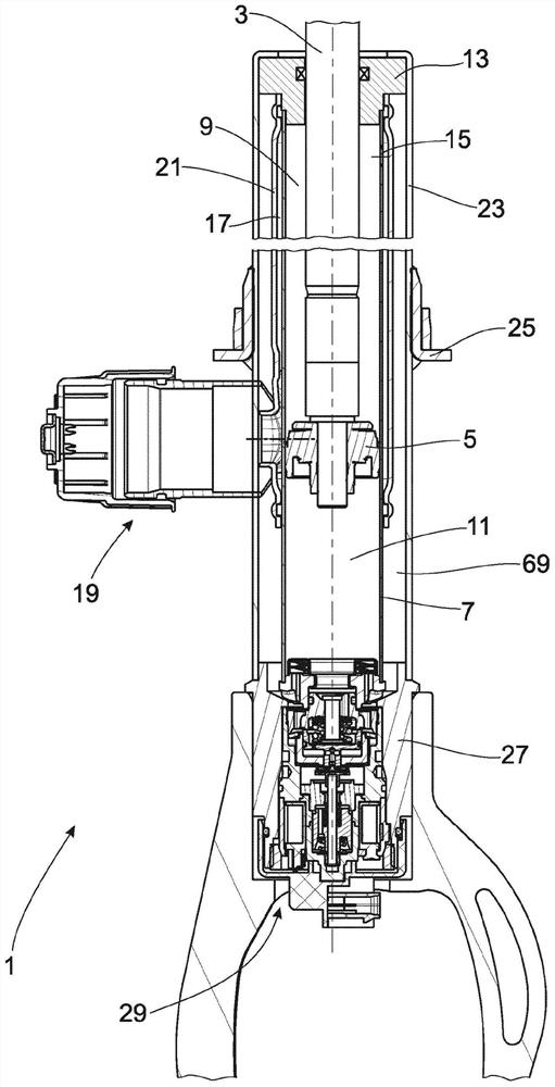
[0021] figure 1 A complete section through a vibration damper 1 with a piston rod 3 with a piston 5 , axially displaceable in an inner cylinder 7 , is shown. Optionally, the piston 5 can be equipped with a damping valve and divide the cylinder 7 into a working space 9 on the piston rod side and a working space 11 remote from the piston rod. The piston rod-side working space 9 is closed at the end by a piston rod guide 13 . Both the working space 9 on the piston rod side and the working space 11 remote from the piston rod are filled with customary hydraulic damping medium.

[0022] The inner cylinder 7 can have an overflow bore 15 which connects the piston rod-side working space 9 with an adjustable damping valve 19 by means of a fluid connection 17 . The fluid connection 17 is formed by an intermediate tube 21 which is pressed tightly against the outer side of the inner cylinder 7 . The inner cylinder 7 as well as the intermediate tube 21 are surrounded by an outer containe...


PUM


Abstract

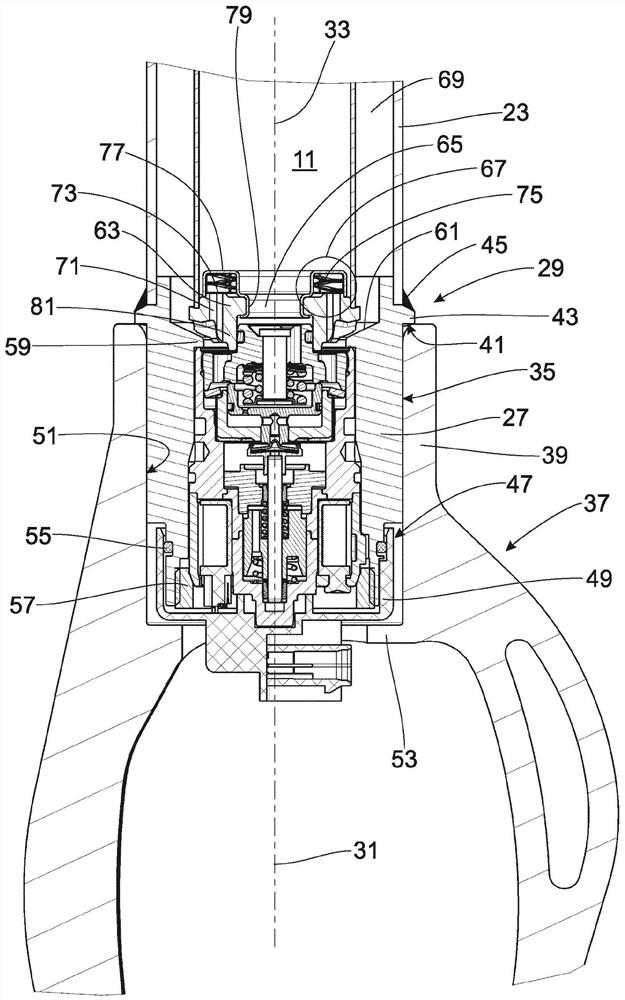
The present invention relates to a vibration damper (1) comprising at least one adjustable damping valve (29) that has an external housing (27) connected to one end of an external container (23) of the vibration damper (1), a longitudinal axis (31) of the adjustable damping valve (29) and a longitudinal axis (33) of the vibration damper (1) extending in parallel, the external housing (27) of the adjustable damping valve (29) having a clamping face (35) for an axle connecting part (37).

Description

technical field [0001] The invention relates to a vibration damper with an adjustable damping valve according to the preamble of patent claim 1 . Background technique [0002] In the case of vibration dampers with adjustable damping valves, especially when the vibration dampers are combined with air springs or are implemented as spring struts with spring retainers for suspension springs, installation space very frequently arises question. In principle, it is also possible to design the adjustable damping valve as a piston valve. More and more frequently, however, there should be damping valves which can be adjusted separately for both directions of movement of the vibration damper. In particular, structural space problems then arise. [0003] DE 40 07 261 A1 describes a vibration damper with adjustable damping force, in which an adjustable damping valve is mounted on the bottom side at the end of the outer container tube. in DE 40 07 261 A1 figure 1 In the illustration ...

Claims


Application Information

Patent Timeline
Patent Type & Authority Applications(China)
IPC IPC(8): F16F9/54F16F9/32B60G13/00F16F9/46
CPCB60G13/005F16F9/3242F16F9/46F16F9/54B60G2204/128B60G2500/10F16F9/34
Inventor T·曼娜L·鲁曼S·施密特M·甘珀特T·索尔夫B·泽斯纳
Owner ZF FIEDRICHSHAFEN AG
Learn More