Unpowered recreation facility sliding protection device
A technology for amusement facilities and protection devices, which is applied in the field of sliding protection devices for non-powered amusement facilities, can solve the problems of tourist safety accidents, affect the effect of buffering, and cannot undertake automatic adjustment of structures, so as to achieve the effect of improving safety and realizing horizontal displacement
- Summary
- Abstract
- Description
- Claims
- Application Information
AI Technical Summary
Problems solved by technology
Method used
Image
Examples
Embodiment 1
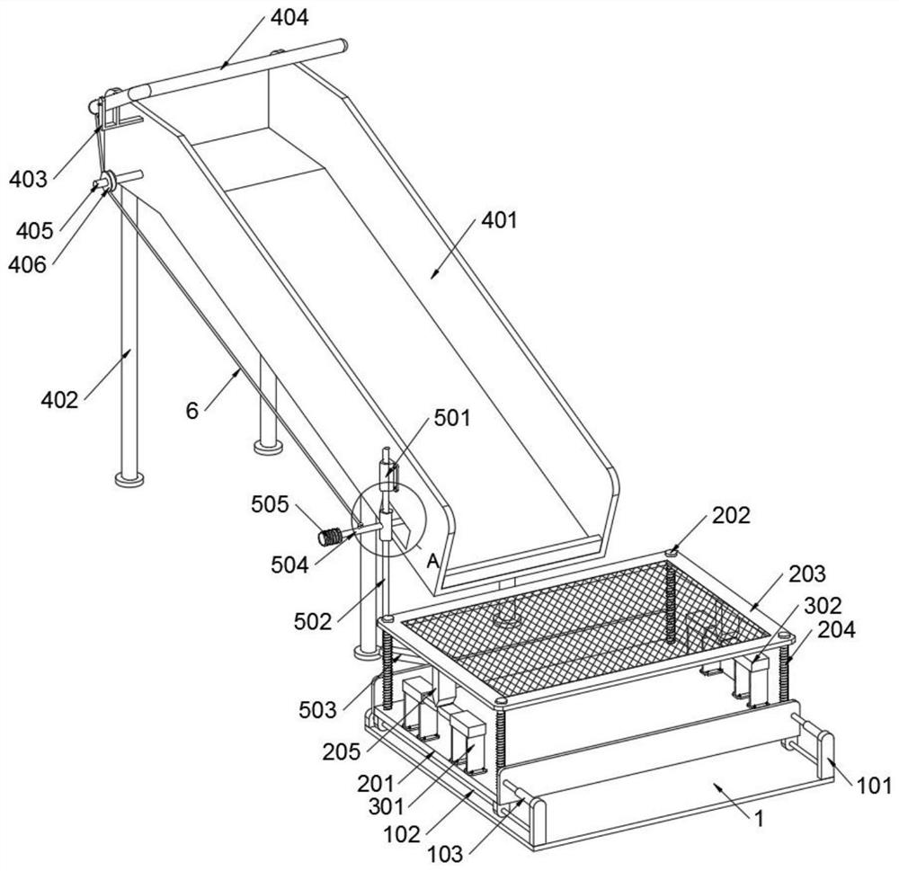
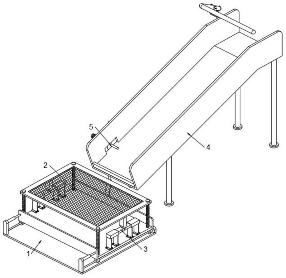
[0033] as attached figure 1 to attach Figure 8 As shown, the non-powered amusement device sliding protection device of the present invention includes a base 1 and a slide structure 4 . The base 1 is fixed on the ground, and a receiving structure 2 is slidably connected to the base 1 , and two shock absorbing structures 3 are installed on the receiving structure 2 . The slide structure 4 is fixed on the ground, and an adjustment structure 5 is installed on the slide structure 4 , and a rope 6 is connected between the slide structure 4 and the adjustment structure 5 . A ride board 7 is placed in the slide structure 4 . Reference as Figure 6 , the receiving structure 2 includes a toggle block 205, there are two toggle blocks 205, and the two toggle blocks 205 are symmetrically welded on the bottom surface of the receiving seat 203, and the heads of the two toggle blocks 205 are pointed structures ; The head end of the toggle block 205 is in contact with the head ends of the...
Embodiment 2
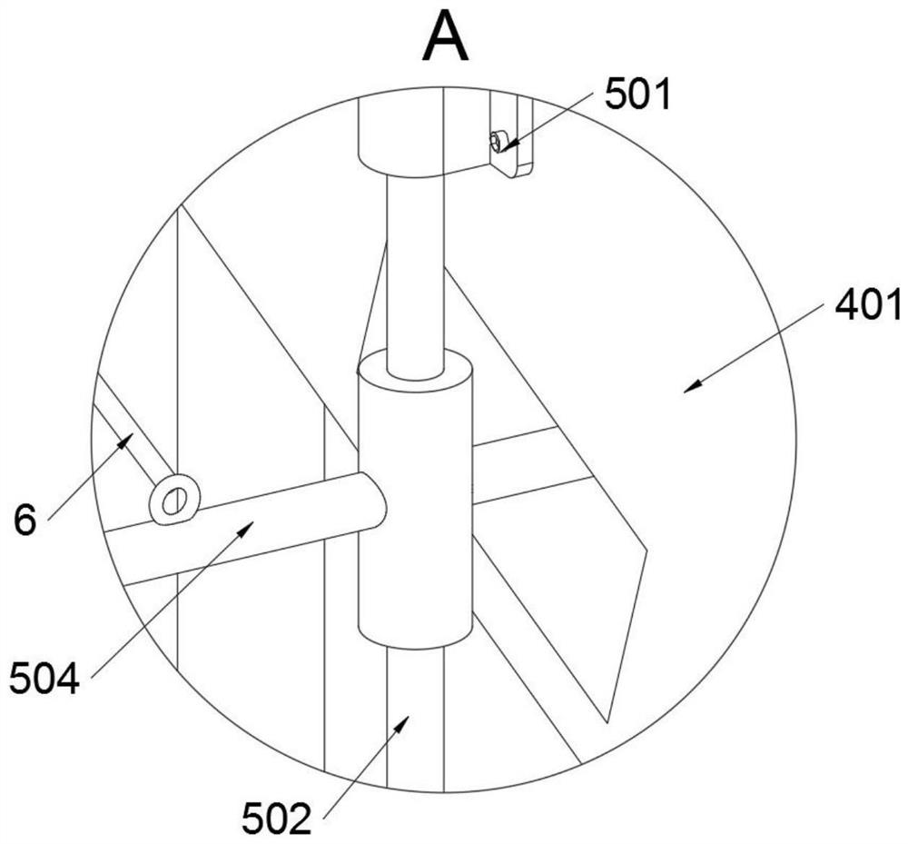
[0038] Reference as Figure 6 , the adjustment structure 5 includes a rotating connection seat B501, a rotating shaft B502 and a toggle lever A503, the rotating connecting seat B501 is fixedly connected to the slide body 401 by bolts, and the rotating connecting seat B501 is rotatably connected with a rotating shaft B502; the rotating shaft B502 is welded with a Toggle the lever A503, and the toggle lever A503 is in contact with the sliding seat 201, so that the sliding seat 201 is in a moving state when the rotating shaft B502 and the toggle lever A503 rotate.
[0039] Reference as Figure 6 , the adjustment structure 5 also includes a toggle lever B504, the toggle lever B504 is welded on the rotating shaft B502, and the toggle lever B504 passes through the slide body 401; when the ride plate 7 slides to the bottom position of the slide body 401 The moving rod B504 is in contact, and at this time the moving rod B504 and the rotating shaft B502 are in a rotating state, so tha...
Embodiment 3
[0042] Reference as Figure 6 , the base 1 also includes elastic damping telescopic rods 103, two elastic damping telescopic rods 103 are provided, and the two elastic damping telescopic rods 103 are welded on the support base A101; The seat 201 is in contact with each other, so that the slow return of the sliding seat 201 after being moved can be realized through the elastic damping telescopic rod 103, and then the phenomenon that the receiving structure 2 has returned to the original position when the tourist has not yet fallen on the receiving structure 2 can be avoided.
PUM
 Abstract
Description
Claims
Application Information
 - R&D
- Intellectual Property
- Life Sciences
- Materials
- Tech Scout
- Unparalleled Data Quality
- Higher Quality Content
- 60% Fewer Hallucinations
Browse by: Latest US Patents, China's latest patents, Technical Efficacy Thesaurus, Application Domain, Technology Topic, Popular Technical Reports.
© 2025 PatSnap. All rights reserved.Legal|Privacy policy|Modern Slavery Act Transparency Statement|Sitemap|About US| Contact US: help@patsnap.com


