Layered storage rack

A storage rack and side rack technology, applied in the storage rack field

Pending Publication Date: 2020-12-25
日照兴业汽车配件股份有限公司
View PDF0 Cites 0 Cited by
  • Summary
  • Abstract
  • Description
  • Claims
  • Application Information

AI Technical Summary

Problems solved by technology

[0004] In view of the above defects, the purpose of the present invention is to provide a layered storage rack, which aims to solve the technical problem that the channel beams in the prior art cannot be efficiently layered.

Method used


Image

  • Layered storage rack
  • Layered storage rack
  • Layered storage rack

Examples


Embodiment Construction

[0026] Below in conjunction with accompanying drawing, further elaborate the present invention.

[0027] The orientations involved in this specification are all based on the orientation of a layered storage rack of the present invention when it is in normal operation, and do not limit its orientation during storage and transportation, and only represent relative positional relationships, not absolute positional relationships.

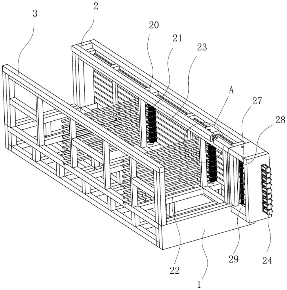
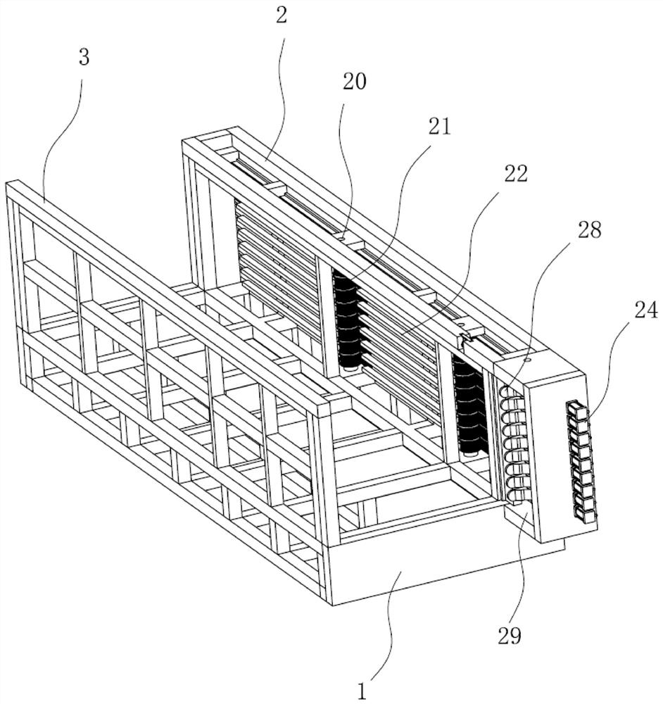
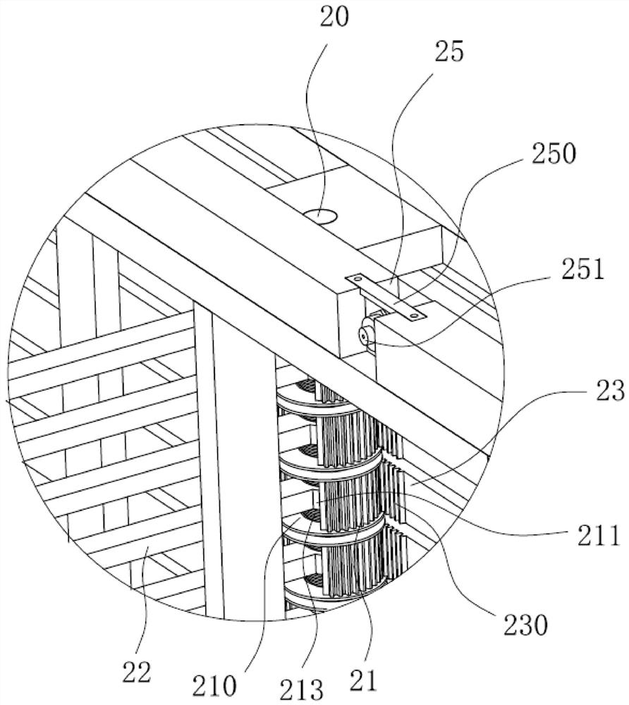
[0028] Such as figure 1 , figure 2 , image 3 , Figure 4 as well as Figure 5 Commonly shown, the layered storage rack includes a bottom frame 1, a first side frame 2 and a second side frame 3 are vertically installed on the bottom frame 1, the first side frame 2 and the second side frame 3 are arranged in parallel and at intervals, and the channel beam Layers are placed between the first side frame 2 and the second side frame 3 .

[0029] Several first connecting shafts 20 are vertically fixedly installed in the first side frame 2, and several f...


PUM


Abstract

The invention discloses a layered storage rack, and relates to the technical field of storage racks. The layered storage rack comprises a bottom frame; a first side frame and a second side frame are vertically installed on the bottom frame; a plurality of first connecting shafts which are arranged at intervals in the length direction of the first side frame are vertically and fixedly installed inthe first side frame; a plurality of first gear sleeves which are arranged at intervals in the axial direction of the first connecting shafts are rotationally installed on the first connecting shafts;stop levers are installed on the first gear sleeves in the radial directions; a plurality of adjusting rods directly facing the first gear sleeves in a one-to-one correspondence manner are horizontally and glidingly installed in the first side frame; first racks meshing with the directly-facing first gear sleeves are arranged on the adjusting rods; and a power assembly for driving the adjusting rods to slide in the reciprocating manner is installed on the first side frame. According to the layered storage rack, the technical problem that channel beams cannot be efficiently stored in a layeredmanner in the prior art is solved. According to the layered storage rack, the stacked channel beams can be automatically separated layer by layer, the layered storage efficiency of the channel beamsis improved, and the storage stability of the layered channel beams is high.

Description

technical field [0001] The invention relates to the technical field of storage racks, in particular to a layered storage rack. Background technique [0002] The placement of the channel beams is mainly to stack on the storage rack. In order to avoid the two layers of channel beams adjacent to each other from being embedded in each other, resulting in the inconvenience of taking and placing the channel beams, it is necessary to horizontally Place two partition bars so that the upper and lower adjacent two-story channel beams can be separated. [0003] At present, the pick-and-place of the partition bars is all done manually, which requires a fixed amount of manpower, resulting in an increase in production costs, and manual work affects the placement of the two partition bars, making the placement of the partition bars inaccurate, resulting in Poor structural stability after palletizing. Contents of the invention [0004] In view of the above defects, the purpose of the pr...

Claims


Application Information

Patent Timeline
IPC IPC(8): B25H3/04
CPCB25H3/04
Inventor 秦兵
Owner 日照兴业汽车配件股份有限公司
Why Eureka
Try Eureka