Self-propelled rail gauge detection structure device for rail detection

A technology of rail detection and detection structure, which is applied in the direction of measuring devices, rails, measuring instruments, etc., can solve the problems of poor applicability, rail adjustment and positioning that cannot be shifted, inconvenient adjustment, etc., and achieve the effect of strong practicability

Inactive Publication Date: 2020-12-25
司俊雄
View PDF7 Cites 4 Cited by
  • Summary
  • Abstract
  • Description
  • Claims
  • Application Information

AI Technical Summary

Problems solved by technology

[0006] The purpose of the present invention is to provide a self-propelled rail gauge detection device. When detecting the rail gauge, although the distance between the rails can be detected by the scale on the detection device and the laser detector, when taking When lowering the detection device, due to the lack of corresponding marks on the monitoring points, it is impossible to accurately adjust and position the offset rails when the workers are repairing and laying adjustments. The standards are different. When testing different gauges, the existing gauge detection device is inconvenient to adjust accordingly for different gauge standards, and the applicability is poor.

Method used


Image

  • Self-propelled rail gauge detection structure device for rail detection
  • Self-propelled rail gauge detection structure device for rail detection
  • Self-propelled rail gauge detection structure device for rail detection

Examples


Embodiment Construction

[0026] Based on the embodiments of the present invention, all other embodiments obtained by persons of ordinary skill in the art without making creative efforts belong to the protection scope of the present invention.

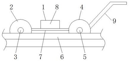
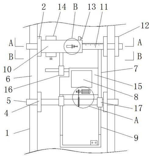
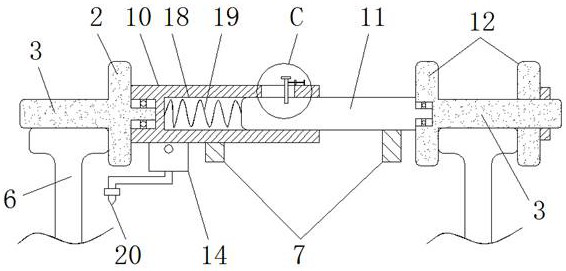
[0027] see Figure 1-8 , the present invention provides a technical solution: a self-propelled rail gauge detection structure device, comprising a detection device body 1, a detection card wheel 2, a detection shaft 3, an auxiliary card wheel 4, an auxiliary shaft 5, a rail 6, Connecting frame 7, control box 8, handrail 9, connecting sleeve 10, connecting rod 11, limit card wheel 12, laser rangefinder 13, paint box 14, mounting plate 15, first connecting sleeve 16, second connecting sleeve 17 , sliding groove 18, support spring 19, spray head 20, motor 21, pulley 22, transmission belt 23, adjustment interface 24, limit rod 25, support frame 26, adjustment rod 27 and ball 28, one side of the detection device body 1 The detection card wheel 2 is provided, and th...


PUM


Abstract

The invention discloses a self-propelled rail gauge detection structure device for rail detection. The self-propelled rail gauge detection structure device comprises a detection device body, a detection clamping wheel, a detection shaft, an auxiliary shaft, connecting frames, a control box, a handrail and a laser range finder; the detection clamping wheel is arranged on one side of the detection device body, and the detection shaft is integrally formed in the middle of the outer side of the detection clamping wheel; the laser range finder is fixed to the front side of the end, close to the connecting rod, of a connecting sleeve; the lower end of the connecting sleeve and the lower end of the connecting rod are connected with one ends of connecting frames in a welded mode, and an installation plate is welded between the two connecting frames; and a control box is installed above the installation plate, and the detection shaft and the auxiliary shaft are located on the upper portion of arail. According to the self-propelled rail gauge detection structure device for rail detection, marking can be conducted on a roadbed where the rail is laid when the rail gauge of the rail is measured, detection personnel can observe the deviation condition of the rail gauge more visually, meanwhile, the detection distance can be adjusted according to rail gauges of different standards, and practicability is high.

Description

technical field [0001] The invention relates to the technical field of rail detection, in particular to a gauge detection structural device for self-propelled rail detection. Background technique [0002] The track gauge detection device is a detection device that detects the distance between the laid rails. It generally walks on the two rails through rollers, and can detect the distance between the two rails through a ruler or a laser detector while walking. The distance between the rails is convenient for laying personnel and maintenance personnel to adjust the installation and daily maintenance of the rails. [0003] But existing gauge detecting device, when using, has following problems: [0004] 1. When detecting the rail gauge, although the distance between the rails can be detected by the scale on the detection device and the laser detector, when the detection device is removed, due to the lack of corresponding marks on the monitoring place , resulting in the inabil...

Claims


Application Information

Patent Timeline
Patent Type & Authority Applications(China)
IPC IPC(8): E01B35/04G01B21/16
CPCE01B35/04G01B21/16
Inventor 司俊雄
Owner 司俊雄
Why Eureka
Try Eureka