
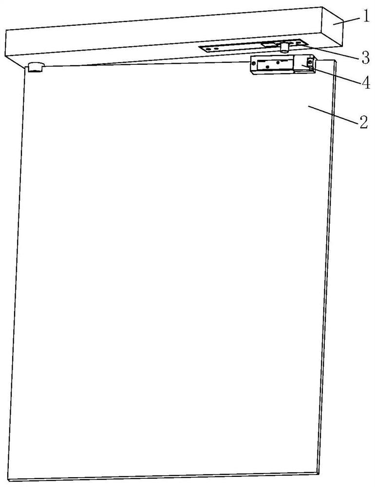
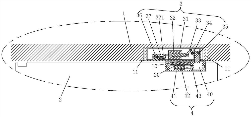
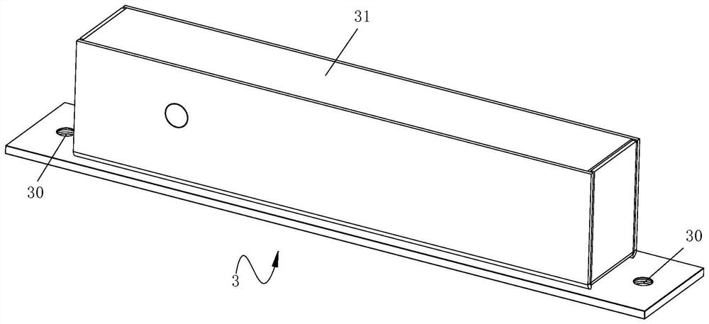
Electric mortise lock and glass door lock

A technology of glass door locks and electric mortise locks, which is applied to building locks, non-mechanical transmission-controlled locks, buildings, etc., can solve the problems of poor stability, unsafe, high heat generation, etc., and achieve ingenious structural design, Good use effect, stable and reliable effect

Pending Publication Date: 2020-12-25
河北爵程安防设备有限公司
View PDF0 Cites 0 Cited by
  • Summary
  • Abstract
  • Description
  • Claims
  • Application Information

AI Technical Summary

Problems solved by technology

Among them, electric mortise locks are generally divided into two categories in the market: one is the power-off opening type, which is used in general access control places to facilitate escape. The disadvantage is that the door can be opened when the power is off, which is not very safe. A lock is very troublesome; the second is the power-off locking type, which is generally used in places with a higher security level. It is locked after power off. This usually requires a spare mechanical key for emergency use, and the installation is more troublesome. In some occasions, there is not enough space to install this kind of lock, and it is not convenient to escape when the power is off.
These two types of locks limit the opening method of the locks due to the structure of the mechanical transmission principle itself, and the locks need to be powered on for a long time to maintain the state
This structure generates a lot of heat and has poor stability.
Moreover, users can only choose one of the structures, and cannot take into account its advantages

Method used


Image

  • Electric mortise lock and glass door lock
  • Electric mortise lock and glass door lock
  • Electric mortise lock and glass door lock

Examples


Embodiment Construction

[0041] It should be noted that, in the case of no conflict, the embodiments of the present invention and the features in the embodiments can be combined with each other.

[0042] In the description of the present invention, it should be noted that the orientation or positional relationship indicated by the terms "upper", "lower", "inner", "back" and the like are based on the orientation or positional relationship shown in the drawings, and are only for It is convenient to describe the present invention and simplify the description, but does not indicate or imply that the device or element referred to must have a specific orientation, be constructed and operate in a specific orientation, and thus should not be construed as limiting the present invention. In addition, the terms "first" and "second" are used for descriptive purposes only, and should not be understood as indicating or implying relative importance.

[0043] The present invention will be described in detail below wi...


PUM


Abstract

The invention provides an electric mortise lock and a glass door lock.The electric mortise lock is arranged on a door frame and comprises a main lock body and a positioning assembly arranged in the main lock body. A first electromagnet for driving a spring bolt to extend out of or retract into the main lock body and an elastic reset part arranged in the main lock body and connected with the springbolt are arranged in the main lock body. A limiting part is constructed at the other end of the first electromagnet relative to one end connected with the spring bolt, the positioning assembly is located at one end of the first electromagnet, the positioning assembly is provided with a limiting end face capable of overturning in a reciprocating manner relative to the main lock body, and the limiting part abuts against the positioning assembly. Under the driving of the first electromagnet, the limiting part pushes the limiting end surface to rotate so as to abut against the limiting end surface in a limiting manner, so that the positioning state of the spring bolt on the main lock body is kept. The electric mortise lock is ingenious in structural design, and the positioning state of the spring bolt can be kept after instant electrification.

Description

technical field [0001] The invention relates to the technical field of electric control locks, in particular to an electric mortise lock. At the same time, the invention also relates to a glass door lock equipped with an electric mortise lock. Background technique [0002] Glass door access control generally uses two kinds of locks, electric mortise lock and magnetic lock. Among them, electric mortise locks are generally divided into two categories in the market: one is the power-off opening type, which is used in general access control places to facilitate escape. The disadvantage is that the door can be opened when the power is off, which is not very safe. A lock is very troublesome; the second is the power-off locking type, which is generally used in places with a higher security level. It is locked after power off. This usually requires a spare mechanical key for emergency use, and the installation is more troublesome. In some occasions, there is not enough space for i...

Claims


Application Information

Patent Timeline
IPC IPC(8): E05B65/00E05B65/06E05B47/06E05B15/00
CPCE05B15/00E05B47/0001E05B47/0002E05B47/0603E05B65/0025E05B65/06E05B2047/0057E05B2047/0086
Inventor 王小朋
Owner 河北爵程安防设备有限公司
Learn More