Automatic lubricating device

An automatic lubricating and lubricating oil technology, which is applied in the direction of engine lubrication, valve devices, quantitative devices, etc., can solve the problems of waste and low work efficiency, and achieve the effect of solving waste, low production cost, and safe and reliable refueling work

Pending Publication Date: 2020-12-25
GUANGXI YUCHAI MASCH CO LTD
View PDF0 Cites 1 Cited by
  • Summary
  • Abstract
  • Description
  • Claims
  • Application Information

AI Technical Summary

Problems solved by technology

[0003] Aiming at the problems existing in the prior art, the present invention provides an automatic lubricating device to solve the problems of easy waste and low work efficiency during the refueling process, while ensuring safe and reliable refueling work

Method used


Image

  • Automatic lubricating device
  • Automatic lubricating device

Examples


Embodiment 1

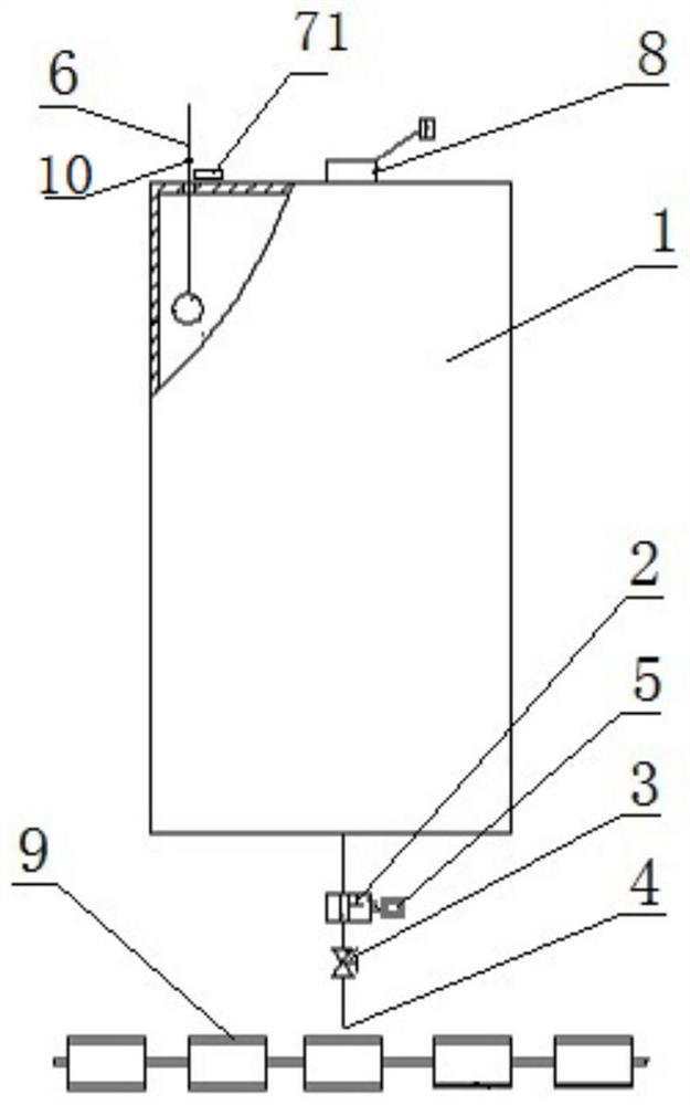
[0020] Such as figure 1 It is an automatic lubricating device, which is used to add lubricating oil to the drag chain engine assembly line, including the oil storage tank 1, the two-position two-way electromagnetic reversing valve 2, and the throttle valve 3 connected in sequence from top to bottom through the oil pipe And the oil nozzle 4 also includes a time relay 5, and the time relay 5 uses two wires to connect the output terminal of the time relay 5 with the input terminal of the two-position two-way electromagnetic reversing valve 2 to control the Describe the opening and closing of the two-position two-way electromagnetic reversing valve 2 valve.

[0021] The working principle of the automatic lubrication device is as follows:

[0022] This device is installed on the side wall below the ditch, and the tow chain 9 directly below the grease nozzle 4 will not affect the normal operation of the tow chain. The lubricating oil in the oil storage tank 1 flows out through the...

Embodiment 2

[0027] On the basis of implementation one, the device also includes an oil level detection mechanism and an oil level alarm 8. The oil level detection mechanism includes an oil dipstick 6 and a first magnetic sensor 71. The oil dipstick 6 is a ruler, and its lower part Insert the oil storage tank 1, the bottom end is fixed with a floating ball, the floating ball is located inside the oil storage tank 1 and floats on the lubricating oil liquid surface, so that the oil dipstick 6 will follow the The amount of lubricating oil inside the oil storage tank 1 moves up and down, and the magnetic ring 10 that cooperates with the first magnetic sensor 71 is fixed on the oil dipstick 6; the first magnetic sensor 71 is fixedly arranged on the storage tank 1 On the outer top surface of the oil tank 1, and on the side of the oil dipstick 6, in other embodiments, the first magnetic sensor 71 can be arranged on the top of the oil storage tank 1 as required, or by using other shapes of oil Sca...

Embodiment 3

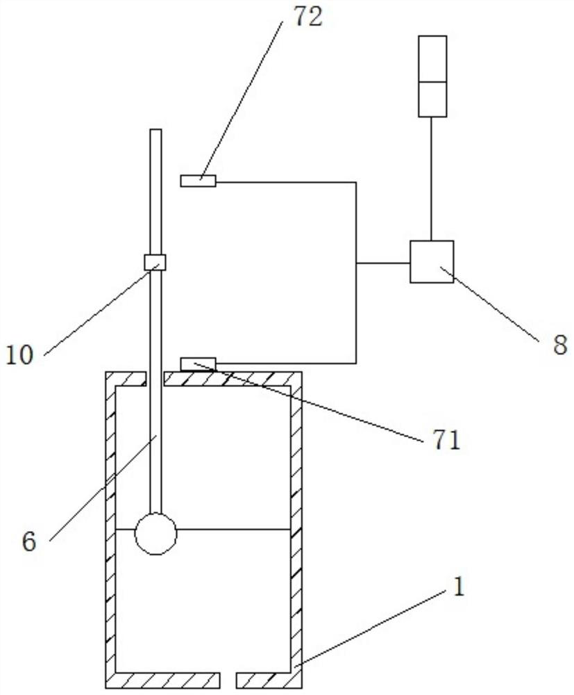
[0029] Such as figure 2 As shown, on the basis of the second embodiment, above the first magnetic sensor 71, a second magnetic sensor 72 that is matched with the magnetic ring 10 is also provided along the side of the oil dipstick 6 running track. When lubricating oil is added to the oil storage tank 1, along with the addition of lubricating oil, the oil dipstick 6 rises with the float, and when the lubricating oil in the oil storage tank 1 reaches the upper limit of the set storage capacity (indicating that the oil storage tank 1 When the amount of lubricating oil inside reaches the maximum oil filling amount), the magnetic ring 10 of the oil dipstick 6 approaches the second magnetic sensor 72, triggering the second magnetic sensor 72 to transmit a signal to the oil level alarm device 8 to realize the purpose of the oil level alarm 8 automatically alarming when the amount of lubricating oil in the oil storage tank 1 reaches the upper limit of the storage capacity.


PUM


Abstract

The invention discloses an automatic lubricating device, and relates to the technical field of engine assembly. The device is used for adding lubricating oil to a ground drag chain type engine assembly line, and is characterized by comprising an oil storage tank (1), a two-position two-way electromagnetic reversing valve (2), a throttle valve (3) and an oil nozzle (4) which are sequentially connected from top to bottom through oil pipes, and further comprising a time relay (5), and the time relay (5) is used for driving opening and closing of the two-position two-way electromagnetic reversingvalve (2). The device realizes automatic lubrication of a ground drag chain to replace current manual operation, solves the problems of easy waste and low working efficiency in an oil adding process,and ensures safe and reliable oil adding work as well.

Description

technical field [0001] The invention relates to the technical field of engine assembly, in particular to an automatic lubricating device. Background technique [0002] The ground drag chain engine assembly line, since the ground drag chain is installed under the trench, currently it is necessary to manually drill into the trench with an oil pot to refuel and lubricate, but the chain is relatively long (about 500 meters), and it takes 40 minutes to run a circle. , the work efficiency is low, and the amount of refueling is difficult to control, which is easy to cause waste. In addition, the space under the trench is narrow and the lighting is insufficient, so there are potential safety hazards for people working in the trench. Contents of the invention [0003] Aiming at the problems existing in the prior art, the present invention provides an automatic lubricating device to solve the problems of easy waste and low work efficiency during the refueling process, while ensurin...

Claims


Application Information

Patent Timeline
Patent Type & Authority Applications(China)
IPC IPC(8): F16N7/02F16N23/00F16N19/00F16N27/02F16N29/04
CPCF16N7/02F16N19/003F16N23/00F16N27/02F16N29/04F16N2210/33F16N2230/10F16N2230/18F16N2250/18F16N2270/20F16N2270/72F16N2280/02
Inventor 龙腾飞龙福海李旭旺梁纪纲
Owner GUANGXI YUCHAI MASCH CO LTD
Why Eureka
Try Eureka