Multichannel multispectral optical filter structure and application and method thereof

A filter and multi-spectral technology, applied in the field of multi-channel multi-spectral filter structure, can solve the problem of affecting the severity of discharge

Active Publication Date: 2020-12-25
NORTH CHINA ELECTRIC POWER UNIV (BAODING)
View PDF19 Cites 3 Cited by
  • Summary
  • Abstract
  • Description
  • Claims
  • Application Information

AI Technical Summary

Problems solved by technology

However, during the observation of serious sparks and arc discharges, the entire imaging range will be covered by discharge spots, which will affect the judgment of the severity of the discharge

Method used


Image

  • Multichannel multispectral optical filter structure and application and method thereof
  • Multichannel multispectral optical filter structure and application and method thereof
  • Multichannel multispectral optical filter structure and application and method thereof

Examples


Embodiment Construction

[0032] The technical solutions in the embodiments of the present invention will be clearly and completely described below in conjunction with the embodiments of the present invention. Obviously, the described embodiments are only some of the embodiments of the present invention, not all of them. Based on the embodiments of the present invention, all other embodiments obtained by persons of ordinary skill in the art without making creative efforts belong to the protection scope of the present invention.

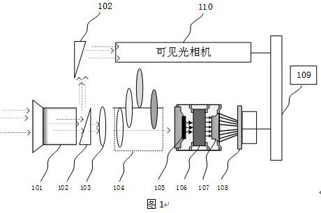
[0033] Depend on figure 1 It can be seen that the multi-spectral solar-blind narrow-band ultraviolet imager includes a lens 101, a spectroscope 102, a standard solar-blind ultraviolet filter 103, a multi-channel multi-spectral filter 104, a photocathode 105, and a microchannel plate (Microchannel plate, MCP ) 106, fiber cone 107, imaging charge-coupled device (Charge-coupled Device, CCD) 108 and image control processing module 109 for image control and processing of ultraviole...


PUM


Abstract

The invention discloses a multichannel multispectral optical filter structure and application and method thereof. The multichannel multispectral optical filter structure comprises an optical filter, aconnecting rod device, a distance measurement disc, and a control end, wherein the optical filter is coaxial with the connecting rod device, one end of the connecting rod device is connected with thedistance measurement disc, and the other end of the connecting rod device is connected with the control end; and the multichannel multispectral optical filter and the coaxial connecting rod device are riveted in a staggered tangent distribution manner.

Description

technical field [0001] The invention belongs to the technical field of solar-blind ultraviolet imaging and discharge diagnosis thereof, and in particular relates to a multi-channel multi-spectral filter structure and its application and method. Background technique [0002] The ultraviolet imaging band of the multi-spectral solar-blind ultraviolet imager is 240-280nm, because when the light in this band of sunlight passes through the atmosphere, its energy is almost exhausted by the scattering of atmospheric molecules and the absorption of the ozone layer. There is no 240-280nm band in the solar spectral distribution, which forms a natural shielding layer, while combustion, explosion and discharge phenomena will emit various spectral bands, including ultraviolet light in the solar blind band. Therefore, through observation, analysis and positioning of solar blind The light in this wavelength band can realize the localization and evaluation of the discharge. [0003] At this...

Claims


Application Information

Patent Timeline
Patent Type & Authority Applications(China)
IPC IPC(8): G02B26/00G03B11/00G01R31/12
CPCG02B26/007G03B11/00G01R31/1218
Inventor 王胜辉律方成牛雷雷
Owner NORTH CHINA ELECTRIC POWER UNIV (BAODING)
Why Eureka
Try Eureka