Eureka AIR delivers breakthrough ideas for toughest innovation challenges, trusted by R&D personnel around the world.

Orthosis device for scoliosis and manufacturing method thereof

A technology for scoliosis and a manufacturing method, which is applied in the directions of orthopedic corsets, medical science, fractures, etc., can solve the problems of insufficient overall strength of the brace to be orthopedic, hindering the normal movement of the spine, and poor orthopedic effect of the brace, etc. It is suitable for popularization and use, the overall structure is simple and convenient, and the orthopedic effect is good.

Active Publication Date: 2020-12-29
XI AN JIAOTONG UNIV
View PDF9 Cites 4 Cited by
  • Summary
  • Abstract
  • Description
  • Claims
  • Application Information

AI Technical Summary

Problems solved by technology

The above-mentioned braces are almost all made of homogeneous materials. Due to the needs of orthopedics, the elastic modulus of the materials is almost greater than that of the wearing limbs. Stress concentration in the application area (that is, the contact area between the brace and the skin) causes skin abrasion and ulceration, which leads to poor orthopedic effect of the brace
Excessively reducing the stiffness of the brace material will lead to the problem that the overall strength of the brace is not enough to perform orthopedics.
Moreover, long-term wearing of the brace may lead to muscle weakness, resulting in dependence on the brace
In addition, fixed braces can also cause joint contractures, hindering the normal movement of the spine

Method used


Image

  • Orthosis device for scoliosis and manufacturing method thereof
  • Orthosis device for scoliosis and manufacturing method thereof
  • Orthosis device for scoliosis and manufacturing method thereof

Examples


Embodiment Construction

[0041] The present invention is further described below in conjunction with accompanying drawing:

[0042] The present invention adopts following technical scheme:

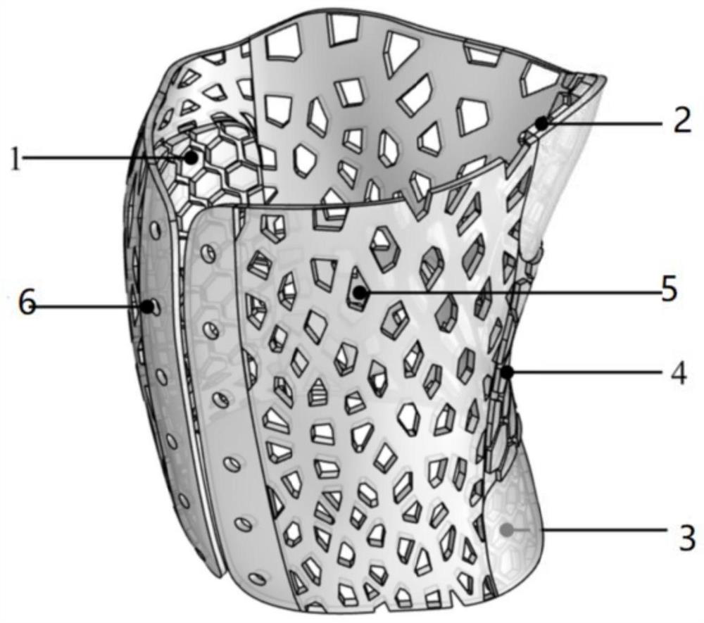
[0043] A full-length anteroposterior CT scan (or MRI scan) of the patient's spine in standing position is performed to establish a three-dimensional digital model of the spine required for orthosis design.

[0044] The data obtained by CT scan (or MRI scan) is processed by Mimics to obtain a three-dimensional digital model in STL format.

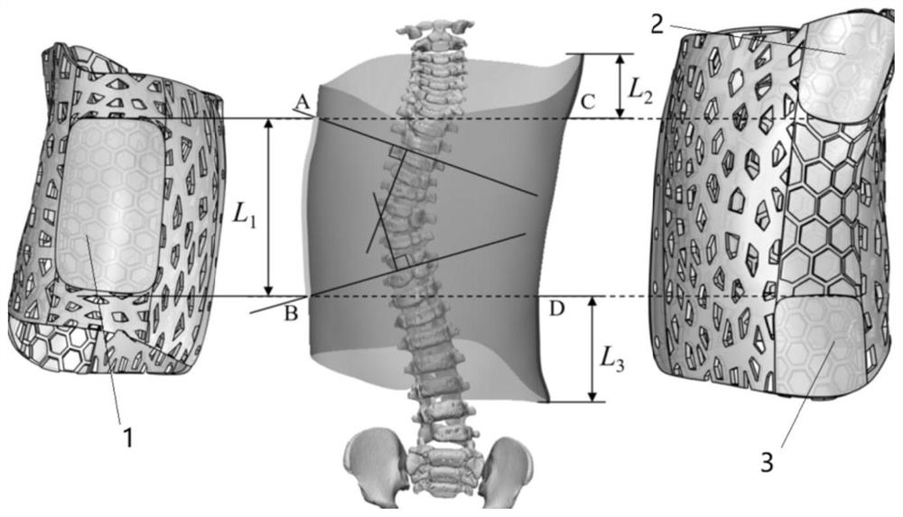
[0045] According to the three-dimensional digital model, the Cobb angle of the patient's scoliosis, and the anterior and posterior axillary lines, the contour design of the orthosis, the delineation of the orthopedic force adjustment structure area, and the design of the block structure were performed.

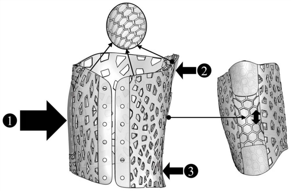
[0046] Orthotics correct scoliosis by applying three points of pressure to the ribs and spine (three-point corrective force system).

[0047] The orthopedic force application ...


PUM


Abstract

The invention discloses an orthosis device for scoliosis and a manufacturing method thereof. The orthosis device comprises an orthosis device body, orthosis structures, a first orthosis force application area, a second orthosis force application area and a third orthosis force application area. The orthosis body is of a cylindrical structure which is provided with a longitudinal opening in one side and attached to the spine section of a human body; openings are formed in the two sides of the orthosis device body; the orthosis structures are arranged in the openings in the two sides; the firstorthosis force application area is arranged on one side of the orthosis device body and located in the middle of the side face where the first orthosis force application area is located; and the second orthosis force application area and the third orthosis force application area are arranged on the other side of the orthosis device body and located at the upper end and the lower end of the side face where the second orthosis force application area and the third orthosis force application area are located respectively to form a three-point type orthosis force system. According to the customizedorthosis device and the design method. The orthosis device can adapt to body surface morphology features and variable stiffness features, and while accurate orthosis can be conducted on an orthosis part of a patient, the frequency of dependence on the orthosis device can be reduced.

Description

technical field [0001] The invention belongs to the technical field of external fixation orthoses, in particular to an orthosis for scoliosis and a manufacturing method thereof. Background technique [0002] Scoliosis is a curvature of one or more segments of the spine laterally deviated from the midline of the body in the coronal plane, forming a curved spinal deformity, usually accompanied by rotation of the spine and kyphosis or protrusion in the sagittal plane increase or decrease. Existing solutions include a series of physical methods such as orthotics, chiropractic, and kinesiology. Reasonable use of non-surgical orthopedic braces can effectively control the development of scoliosis when the age is young and the Cobbs angle is less than 45°. However, the orthotics used for orthopedic braces need to adjust the orthopedic stress in stages according to different stages of orthopedics. Currently, commonly used thoracolumbosacral braces such as Charleston flexion brace, ...

Claims


Application Information

Patent Timeline
Patent Type & Authority Applications(China)
IPC IPC(8): A61F5/058A61F5/02
CPCA61F5/058A61F5/02
Inventor 李宏伟李涤尘杨张凯黄桂林李智凯
Owner XI AN JIAOTONG UNIV
Why Eureka
Eureka Blog
Learn More