Multipurpose vehicle-mounted bracket fixed on vehicle roof

A technology of roof and inclined struts, which is applied to vehicle components, transportation and packaging, etc., can solve the problem of easy and convenient rest and entertainment, single function and fixing method, and the inability to adjust the roof and front seat pillow and tablet computer. Fixed and other issues to achieve a stable and smooth installation process

Active Publication Date: 2020-12-29
巫山县悦梦达机动车检测有限公司
View PDF5 Cites 0 Cited by
  • Summary
  • Abstract
  • Description
  • Claims
  • Application Information

AI Technical Summary

Problems solved by technology

[0003] However, the functions and fixing methods of the tablet computer vehicle mount in the prior art are relatively single, and the position between the roof and the front seat pillow can not be used to realize the multi-dimensional adjustment and fixing of the tablet computer, which cannot be used for long-distance self-driving tours. Passengers and drivers provide a more relaxed and convenient way of rest and entertainment; therefore, the present invention provides a multi-purpose car mount fixed on the roof to solve the above problems

Method used


Image

  • Multipurpose vehicle-mounted bracket fixed on vehicle roof
  • Multipurpose vehicle-mounted bracket fixed on vehicle roof
  • Multipurpose vehicle-mounted bracket fixed on vehicle roof

Examples


Embodiment 1

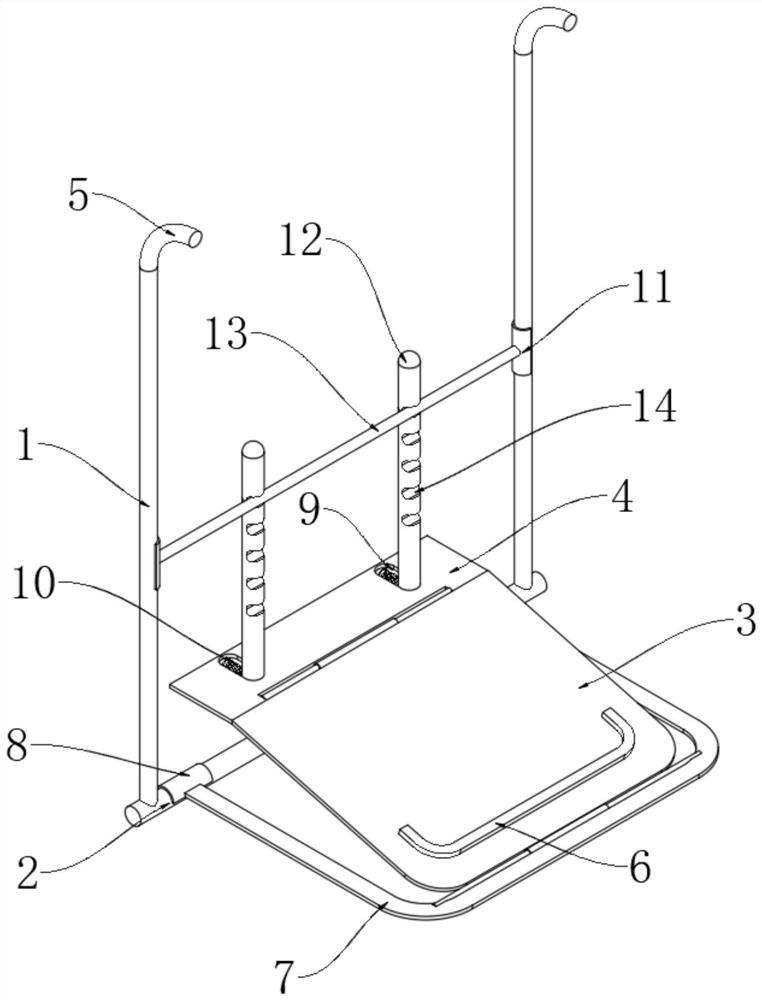
[0036]SeeFigure 1-2 , A multi-purpose vehicle mount fixed on the roof, comprising a first bracket 3, the front end of the first bracket 3 is rotatably connected in the first transverse frame 7 through a rotating shaft, and the rear end of the first bracket 3 is rotatably connected with an adjusting plate 4 through a rotating shaft; Both ends of the first horizontal frame 7 on the same side are fixedly connected with a clamping half ring A8, the clamping half ring A8 is movably clamped on the horizontal strut 2, and both ends of the horizontal strut 2 are fixedly connected with vertical struts 1;

[0037]Two adjustment grooves 9 are opened on the adjustment plate 4, an adjustment rod 12 is slidably connected in the adjustment groove 9, and one side of the adjustment rod 12 is slidably connected to the adjustment groove 9 through an adjustment spring 10;

[0038]A plurality of clamping grooves 14 are opened on the front side of the adjusting rod 12, and a clamping column 13 is arranged betw...

Embodiment 2

[0042]SeeFigure 3-4 , The difference based on Example 1 is:

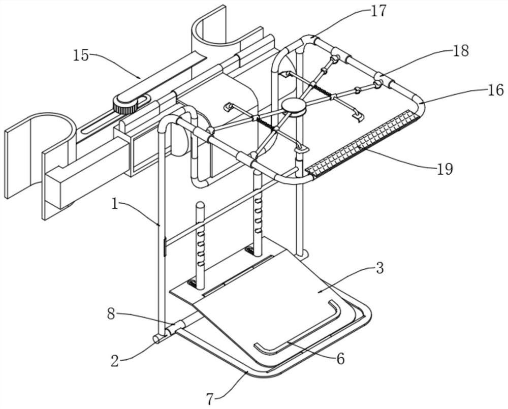
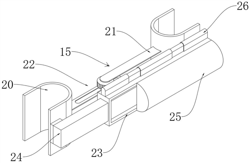
[0043]The upper end of the vertical support rod 1 is movably clamped with a connecting tube 5, and the connecting tube 5 is fixedly connected with a connecting tube sleeve 17 outside, a U-shaped frame 33 is fixedly connected between the two connecting tube sleeves 17, and the upper side of the U-shaped frame 33 is fixedly connected at the center. There is an arc-shaped connecting plate 27, a U-shaped ferrule 28 is fixedly connected to the upper rear side of the arc-shaped connecting plate 27, and the U-shaped ferrule 28 is movably clamped on the installation mechanism 15.

[0044]The installation mechanism 15 includes a mounting seat 26. The U-shaped ferrule 28 is movably clamped on the upper center of the mounting seat 26. The lower end of the mounting seat 26 is fixedly connected with a mounting frame 23; a mounting rod 24 is movably inserted in the mounting frame 23, and the mounting rod 24 and The side of the U-shaped block...

Embodiment 3

[0047]SeeFigure 5-8 , The difference based on Example 1-2 is:

[0048]A second horizontal frame 16 is fixedly connected between the front sides of the connecting pipes 5 on both sides, and a connecting shaft sleeve 18 is movably connected to the second horizontal frame 16; the front end of the second horizontal frame 16 is fixedly connected with a magnetic plate 19 and a magnetic plate 19 It attracts the roof of the vehicle; there are four connecting shaft sleeves 18, of which two connecting shaft sleeves 18 on one side are fixedly connected to the inner side of the first spherical shell 36. The first spherical shell 36 is movably connected with the first sphere, the first sphere The second spherical shell 37 is fixedly connected with the connecting rod;

[0049]A second ball 46 is movably connected in the second spherical shell 37, and the second ball 46 is fixedly connected to the end of the second inclined support rod 40; the second inclined support rods 40 are all rotatably connected ...


PUM


Abstract

The invention discloses a multipurpose vehicle-mounted support fixed to a vehicle roof, and belongs to the technical field of vehicle-mounted supports. The multipurpose vehicle-mounted support fixed to the vehicle roof comprises a first support, the front end of the first support is rotationally connected into a first transverse frame through a rotating shaft, and the rear end of the first supportis rotationally connected with an adjusting plate through a rotating shaft; clamping semi-rings A are fixedly connected to the two end parts of the same side of the first transverse frame, the clamping semi-rings A are movably clamped on transverse supporting rods, and vertical supporting rods are fixedly connected to the upper sides of the two ends of the transverse supporting rods; and two adjusting grooves are formed in the adjusting plate, adjusting rods are slidably connected into the adjusting grooves, and one sides of the adjusting rods are slidably connected with the adjusting groovesthrough adjusting springs. The multipurpose vehicle-mounted support fixed to the vehicle roof solves the problem that in the prior art, a tablet personal computer support cannot achieve multi-dimensional adjustment and fixation of a tablet personal computer through the position between a vehicle roof and a front-row seat pillow.

Description

Technical field[0001]The present invention relates to the technical field of vehicle mounts, in particular to a multi-purpose vehicle mount fixed on the roof of a vehicle.Background technique[0002]With the increasing popularity of mobile terminals, tablet computers have become an indispensable part of people’s daily life, leisure, and entertainment, and are the main tools most people use for office and entertainment; especially during driving, passengers in the back usually need to use them. Tablet computers pass the time. Since most of the tablet computers are slightly larger in size and weight, in order to be more convenient and easy to use, a car holder fixed on the front seat pillow is derived to fix the tablet computer.[0003]However, the function and fixing method of the tablet computer car holder in the prior art are relatively single, and the position between the roof and the front seat pillow can not be used to realize the multi-dimensional adjustment and fixing of the table...

Claims


Application Information

Patent Timeline
Patent Type & Authority Applications(China)
IPC IPC(8): B60R11/02
CPCB60R11/0252B60R2011/0017B60R2011/0028B60R2011/008B60R2011/0068B60R2011/0056B60R2011/0071
Inventor 张帅余永涛张奇
Owner 巫山县悦梦达机动车检测有限公司
Why Eureka
Try Eureka