Unmanned aerial vehicle booster rocket thrust line and gravity center deviation measuring device and method
A rocket thrust and deviation measurement technology, applied in the field of unmanned aerial vehicles, can solve the problems of inconsistent oil core position, inconvenient reading, poor pressure bearing performance, etc., and achieve the effects of preventing uncontrolled rollover, good practicability and simple structure
- Summary
- Abstract
- Description
- Claims
- Application Information
AI Technical Summary
Problems solved by technology
Method used
Image


Examples
Embodiment 1
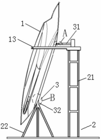
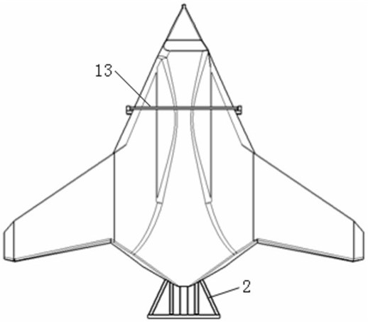
[0043] This embodiment discloses a device for measuring the deviation between the thrust line and the center of gravity of a UAV-assisted rocket. figure 1 , figure 2 and Figure 7 , the measuring device is connected with the UAV 1, and mainly includes a supporting part 2 and a measuring part 3, and the supporting part 2 includes a first supporting frame 21 and a second supporting frame 22, and the two supporting frames are perpendicular to each other, and Fixed on the ground by the bottom plate, the measuring part 3 includes a first measuring mechanism 31 and a second measuring mechanism 32, the first measuring mechanism 31 is arranged on the first supporting frame 21 and connected with the supporting joint 4 of the UAV 1, It is used to support the UAV 1 laterally and measure the lateral support force. The support joint 4 is the fuselage structure of the UAV 1. It is used to support and fix the UAV 1 when it is placed horizontally. It measures the UAV center of gravity 14 an...
Embodiment 2
[0045] This embodiment discloses a device for measuring the deviation between the thrust line and the center of gravity of a UAV-assisted rocket. Figure 4-Figure 8 , on the basis of Embodiment 1, in order to better realize the present application, the side of the thrust cone 5 is provided with a through side hole, and a rotating shaft 7 is installed in the side hole, and the two ends of the rotating shaft 7 extend to the outside of the side hole And bearing 8 is installed respectively, and bearing 8 is arranged in the U-shaped groove on the second support frame 22, and bearing 8 is the rotating mechanism that fixes rotating shaft 7 on the second support frame 22, and the rotational friction coefficient of bearing 8 is little, can eliminate Influencing factors of friction, the part where the second support frame 22 is in contact with the thrust cone is provided with an escape groove 9, and the UAV 1 can rotate around the rotating shaft 7.
[0046] Further, in order to better r...
Embodiment 3
[0055] This embodiment discloses a method for measuring the deviation between the thrust line and the center of gravity of a UAV-assisted rocket. Figure 1-8 , including the following steps:
[0056] S1. First, the support member 2 is fixed on the ground, and then the pressure sensor 312 and the force-measuring joint 313 are respectively installed at the end of the telescopic rod 311 on the first support frame 21, and the guardrail 13 on the first support frame 21 is installed at the same time. Open;
[0057] S2. Set the sensor mounting seat 10 on the thrust cone 5, the two are pasted by the cone surface and the sensor mounting seat 10 is fixedly connected with the base flange 6 on the thrust cone 5 by using locking bolts, and then on the sensor mounting seat 10 Install the inclination sensor 321 and the counterweight 11 at both ends respectively, then install the rotating shaft 7 through the side hole of the thrust cone 5, and install the bearing 8 at the two ends of the rot...
PUM
 Abstract
Description
Claims
Application Information
 - Generate Ideas
- Intellectual Property
- Life Sciences
- Materials
- Tech Scout
- Unparalleled Data Quality
- Higher Quality Content
- 60% Fewer Hallucinations
Browse by: Latest US Patents, China's latest patents, Technical Efficacy Thesaurus, Application Domain, Technology Topic, Popular Technical Reports.
© 2025 PatSnap. All rights reserved.Legal|Privacy policy|Modern Slavery Act Transparency Statement|Sitemap|About US| Contact US: help@patsnap.com