A built-in anti-drop beam device

An anti-drop beam, embedded technology, used in bridges, bridge construction, bridge parts and other directions, can solve problems such as beam damage, and achieve the effect of avoiding damage

Active Publication Date: 2021-11-09
INST OF ENG MECHANICS CHINA EARTHQUAKE ADMINISTRATION
View PDF9 Cites 0 Cited by
  • Summary
  • Abstract
  • Description
  • Claims
  • Application Information

AI Technical Summary

Problems solved by technology

[0003] The present invention intends to provide a built-in anti-falling beam device to solve the problem that the anti-falling beam facility and the beam body have a hard impact during an earthquake, which is easy to cause damage to the beam body

Method used


Image

  • A built-in anti-drop beam device
  • A built-in anti-drop beam device
  • A built-in anti-drop beam device

Examples


Embodiment

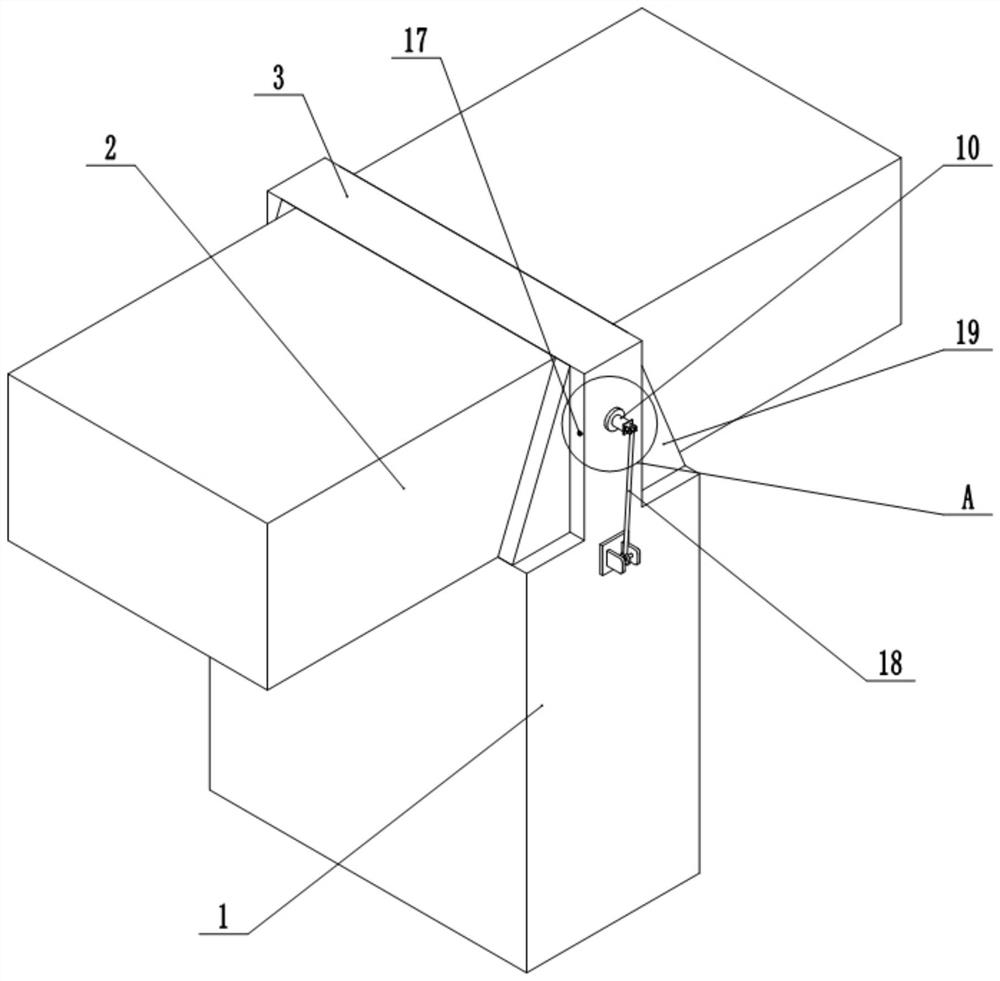
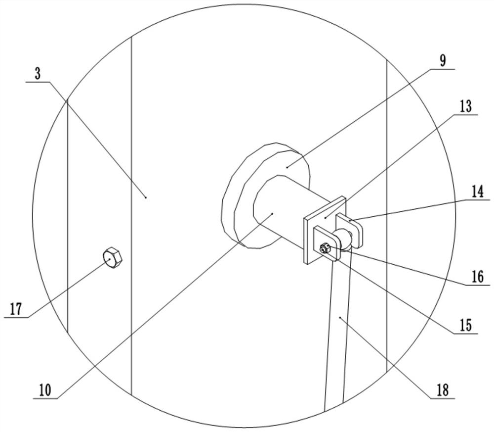
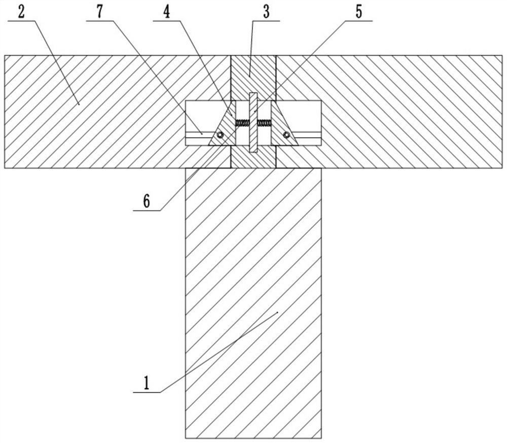
[0022] like figure 1 , figure 2 , image 3 , Figure 4 , Figure 5 and Image 6 As shown: an embedded anti-beam device including a pier 1, a partition plate 3 is fixed on the upper surface of the bridge 1, and the separator 3 is perpendicular to the bridge 1, and the separator 3 is provided with a horizontal set channel, in the channel The horizontally sliding connection of the finite column 4, and the end faces of the limit column 4 extend out of the channel, and the end faces of the limit column 4 are inclined inwardly, and vertical arrangement is vertically disposed on the limit column 4. The outer wall of the positioning column 5 is in contact with the outer wall of the positioning column 5, and the two ends of the positioning column 5 are connected to the inner wall of the passage, and the two ends of the chute are fixed to the positioning column 5. The spring 6 is placed on the bridge 1, and the beam body 2 is placed on the partition 3 symmetry, and the upper surface of the beam...

specific Embodiment approach

[0023] After the left side beam body 2 is lifted, the left end beam body 2 is placed in the process, and the beam body 2 is pressed down the inclined surface of the left end of the limit post 4, so that the limit column 4 slides to the right, the left end beam body 2 reaches the designation After the position, the limit column 4 slides in the initial position in the spring 6 and the positioning column 5, and the left end of the limit column 4 extends into the cavity of the left side beam 2; during this process, the limit column 4 left ends The limit rod 8 on the side slides into the groove in the inner wall of the cavity, until the limit rod 8 is in contact with the limit slot 7, at which time the limit rod 8 is elapsed and extension under the action of the spring 6. In the groove 7; after the right side beam body 2 is lifted, placed in the designated position, the right end beam body 2 is placed in the process, the beam body 2 extruded the inclined surface of the right end of the...


PUM


Abstract

The invention relates to the field of bridge construction, and specifically discloses a built-in anti-drop beam device, which includes a bridge pier, a partition plate is fixed on the upper surface of the bridge pier, the partition plate is perpendicular to the bridge pier, and a horizontally arranged through groove is opened on the partition plate. The inner horizontal slide is connected with the limit column, the two ends of the limit column protrude from the through groove, the end faces of the two ends of the limit column are all inclined inwardly, the limit column is provided with a vertical chute, and the chute is vertically provided with Positioning column, the diameter of the positioning column is in contact with the side wall of the chute, the two ends of the positioning column pass through the limit column and connect with the inner wall of the channel, the two ends of the chute are fixed with springs facing the positioning bar; Segmental beam body, the beam body is placed symmetrically with respect to the partition, and the upper surface of the beam body is flush with the upper surface of the partition board, and the ends of the beam body are provided with cavities, and the inner diameter of the cavity is equal to the outer diameter of the limiting column The present invention intends to solve the problem that the anti-falling beam facilities and the beam body are hard hit during an earthquake, which is easy to cause damage to the beam body.

Description

Technical field [0001] The present invention relates to the field of bridge construction techniques, and a embedded anti-slave device is disclosed. Background technique [0002] my country is one of the world's most powerful and earthquake disasters. The beam is one of the highest frequencies, the most destructive bridge, the most difficult bridge. The damage form of the earthquake on the upper structure of the bridge includes the destruction of the beam, the collision damage, and the mount separated from its guide grooves or bottom basins, and loss of horizontal load capacity. The main constructor of the conventional defense beam is to provide concrete block, anchor or steel bracket on both sides of the upper portion of the pier, and the bridge prevents the beam from falling off, but because the cushioning device is not set, the beam is shocked when the earthquake The facility is a hard impact with the beam body, which is easy to damage the beam body. Inventive content [0003]...

Claims


Application Information

Patent Timeline
Patent Type & Authority Patents(China)
IPC IPC(8): E01D19/00
CPCE01D19/00
Inventor 孙得璋何先龙戴君武张昊宇李思汉
Owner INST OF ENG MECHANICS CHINA EARTHQUAKE ADMINISTRATION
Why Eureka
Try Eureka