Magnetic suspension bearing stator, magnetic suspension bearing and compressor

A technology of magnetic suspension bearing and bearing stator, applied in the direction of magnetic bearing, bearing, shaft and bearing, can solve the problem of low machining accuracy, and achieve the effect of improving the low machining accuracy

Active Publication Date: 2021-01-01
GREE ELECTRIC APPLIANCES INC OF ZHUHAI
View PDF5 Cites 3 Cited by
  • Summary
  • Abstract
  • Description
  • Claims
  • Application Information

AI Technical Summary

Problems solved by technology

[0008] The present invention aims to provide a magnetic suspension bearing stator, a magnetic suspension bearing and a compressor, so as to improve the problem in the related art that the processing accuracy of the stator core is not high when it is shrunk into the housing.

Method used


Image

  • Magnetic suspension bearing stator, magnetic suspension bearing and compressor
  • Magnetic suspension bearing stator, magnetic suspension bearing and compressor
  • Magnetic suspension bearing stator, magnetic suspension bearing and compressor

Examples


Embodiment Construction

[0030] The following will clearly and completely describe the technical solutions in the embodiments of the present invention with reference to the accompanying drawings in the embodiments of the present invention. Obviously, the described embodiments are only some, not all, embodiments of the present invention. The following description of at least one exemplary embodiment is merely illustrative in nature and in no way taken as limiting the invention, its application or uses. Based on the embodiments of the present invention, all other embodiments obtained by persons of ordinary skill in the art without creative efforts fall within the protection scope of the present invention.

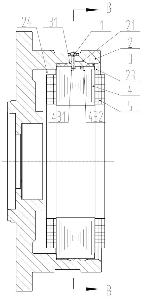
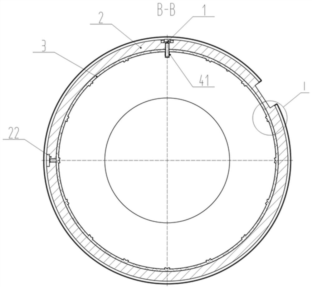
[0031] figure 2 A structural schematic diagram showing a longitudinal section of the magnetic suspension bearing of this embodiment; image 3 show figure 2 The structural schematic diagram of the cross-section at B-B of the magnetic suspension bearing shown.

[0032] combine figure 2 and 3 As...


PUM


Abstract

The invention relates to a magnetic suspension bearing stator, a magnetic suspension bearing and a compressor. The magnetic suspension bearing stator comprises a stator core (4), a stator coil (5), ashell (2) and a filling and sealing member (3); the stator coil (5) is wound around the stator iron core (4); the shell (2) sleeves outside the stator iron core (4) and is in clearance fit or transition fit with the stator iron core (4); and the filling and sealing member (3) fills between the shell (2) and the stator core (4). According to the technical scheme, the stator iron core and the shellare in clearance fit or transition fit, so that the problem that in the prior art, because the stator iron core is arranged in the shell in a hot sleeving manner, the machining precision is not high is solved.

Description

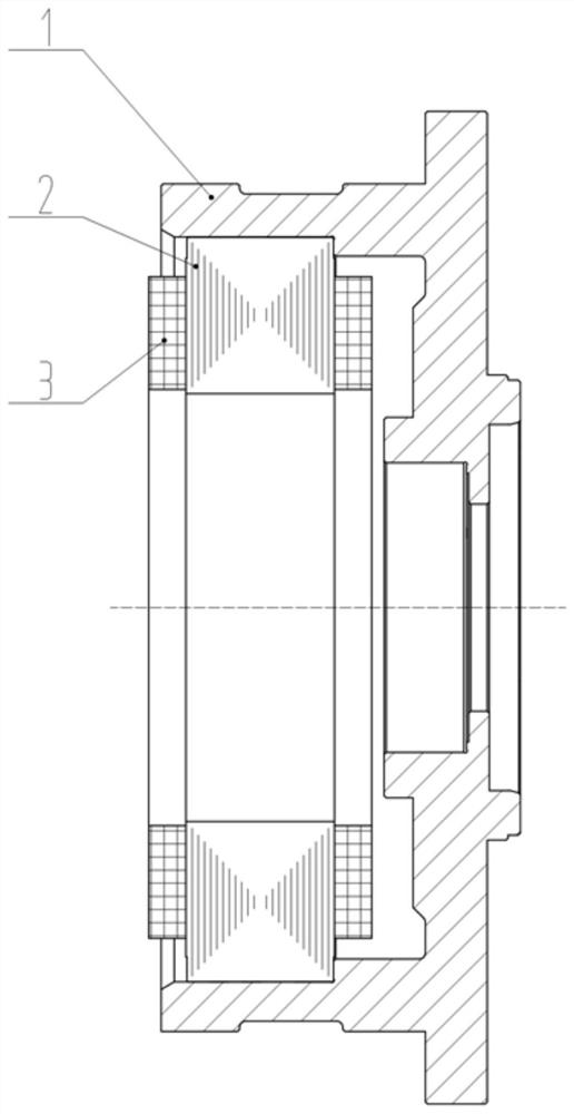
technical field [0001] The invention relates to the field of electrical equipment, in particular to a magnetic suspension bearing stator, a magnetic suspension bearing and a compressor. Background technique [0002] Different from traditional rolling bearings and sliding bearings, magnetic suspension bearings use electromagnetic force or permanent magnetic force to suspend rotating parts in the air and maintain a non-contact state with other objects. They have excellent performances such as high precision, high speed, no lubrication, and low loss. . Such as figure 1 As shown, the stator assembly of a radial magnetic levitation assembly includes a radial stator core 2, a housing 1 for installing the radial stator core, and a coil 3 wound on the magnetic poles of the radial stator core. The stator core 2 and the housing 1 mostly adopt an interference fit to ensure their circumferential and axial positioning. Put the stator core 2 into the heated shell 1 to ensure the interf...

Claims


Application Information

Patent Timeline
IPC IPC(8): F16C32/04
CPCF16C32/047F16C32/044F16C32/0461F16C2226/32F16C2380/26F16C2202/22F16C2240/46
Inventor 郭伟林张芳龚高张超李欣梁豪
Owner GREE ELECTRIC APPLIANCES INC OF ZHUHAI
Why Eureka
Try Eureka