OLED light-emitting unit, OLED substrate and manufacturing method of OLED light-emitting unit

A light-emitting unit and a technology of a manufacturing method, which are applied in the fields of electrical components, semiconductor/solid-state device manufacturing, semiconductor devices, etc., can solve problems such as brightness reduction, and achieve the effect of reducing visual differences

Active Publication Date: 2021-01-01
BOE TECH GRP CO LTD +1
View PDF4 Cites 3 Cited by
  • Summary
  • Abstract
  • Description
  • Claims
  • Application Information

AI Technical Summary

Problems solved by technology

Due to the microcavity optics, the color of the OLED device will change with the viewing angle, and the brightness usually decreases

Method used


Image

  • OLED light-emitting unit, OLED substrate and manufacturing method of OLED light-emitting unit
  • OLED light-emitting unit, OLED substrate and manufacturing method of OLED light-emitting unit
  • OLED light-emitting unit, OLED substrate and manufacturing method of OLED light-emitting unit

Examples


Embodiment Construction

[0029] In order to make the purpose, technical solutions and advantages of the embodiments of the present invention more clear, the following will clearly and completely describe the technical solutions of the embodiments of the present invention in conjunction with the drawings of the embodiments of the present invention. Apparently, the described embodiments are some, not all, embodiments of the present invention. All other embodiments obtained by those skilled in the art based on the described embodiments of the present invention belong to the protection scope of the present invention.

[0030] In the description of the present invention, it should be noted that the terms "center", "upper", "lower", "left", "right", "vertical", "horizontal", "inner", "outer" etc. The indicated orientation or positional relationship is based on the orientation or positional relationship shown in the drawings, and is only for the convenience of describing the present invention and simplifying...


PUM

PropertyMeasurementUnit
thicknessaaaaaaaaaa
thicknessaaaaaaaaaa
thicknessaaaaaaaaaa

Abstract

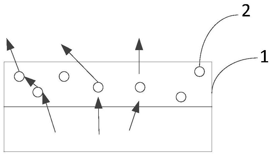
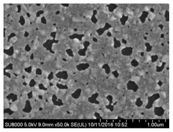
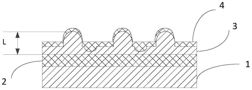
The invention relates to an OLED light-emitting unit, which is used for an OLED substrate for top light emission and comprises an anode, a cathode and an organic functional layer located between the anode and the cathode. The anode comprises a first metal layer and a second metal layer which are arranged in sequence, and an isolation layer is arranged between the first metal layer and the second metal layer. The thickness of the second metal layer is within a preset threshold range, so that metal atoms of the second metal layer can be subjected to thermal agglomeration under a preset conditionand are rearranged to form a concave-convex structure on the surface of the second metal layer. The invention further relates to an OLED display substrate and a manufacturing method of the OLED light-emitting unit.

Description

technical field [0001] The invention relates to the technical field of manufacturing display products, in particular to an OLED light-emitting unit, an OLED substrate and a method for manufacturing the OLED light-emitting unit. Background technique [0002] OLED (Organic Light-Emitting Diode, organic light-emitting diode) display technology has the characteristics of self-illumination, wide viewing angle, wide color gamut, high contrast, light and thin, foldable, bendable, light and portable, etc., and has become the main direction of research and development in the display field. Due to the microcavity optics, OLED devices have a certain change in color with viewing angle, and the brightness usually decreases. Now more and more people are using curved screens, and curved screens can observe the front viewing angle and the large side viewing angle of the screen at the same time, so the requirements for the viewing angle and L-decay (brightness attenuation) of the screen are ...

Claims


Application Information

Patent Timeline
Patent Type & Authority Applications(China)
IPC IPC(8): H01L51/52H01L51/56
CPCH10K50/813H10K50/81H10K50/854H10K50/856H10K71/00H10K50/816Y02B20/30H10K2102/103H10K2102/3026
Inventor 张伟曾诚卿万梅李金钰廖兵
Owner BOE TECH GRP CO LTD
Why Eureka
Try Eureka