Winder with winding speed slowing mechanism

A cord reel and line speed technology, which is applied in the field of cord reels with a mechanism for slowing down the reeling speed, can solve the problems of touching other objects, easily hurting users, falling off the power cord, etc., to improve safety and stability, the effect of reducing the take-up speed and slowing down the rotation speed

Pending Publication Date: 2021-01-05
SUZHOU CHUNJU ELECTRIC CO LTD
View PDF0 Cites 0 Cited by
  • Summary
  • Abstract
  • Description
  • Claims
  • Application Information

AI Technical Summary

Problems solved by technology

[0003] However, this type of take-up method mainly has the following disadvantages: during the reset process, the inertia of the coil spring is getting bigger and bigger, resulting in faster and faster take-up speed, resulting in the swing of the power plug, which is easy to hurt the user or touch it. Other items, even the power cord falls off due to collision with the body

Method used


Image

  • Winder with winding speed slowing mechanism
  • Winder with winding speed slowing mechanism
  • Winder with winding speed slowing mechanism

Examples


Embodiment 1

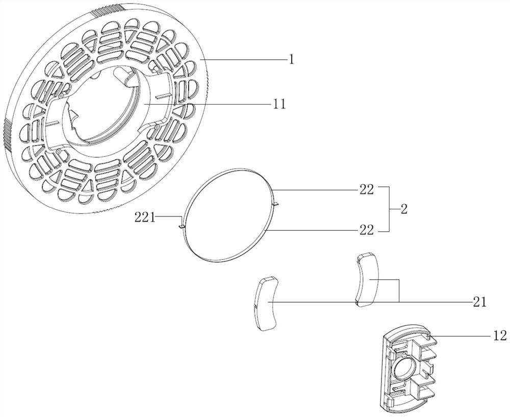
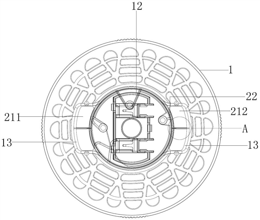
[0025] see Figure 1 to Figure 4 , the figure shows a wire reel provided by an embodiment of the present invention with a winding speed slowing mechanism, which mainly includes a wire reel 1 and a deformable ring 2, and the wire reel 1 is rotatably installed on On the winding support, the winding support has a support insert 12 embedded in the central circular hole 11 of the winding reel 1, and the deformable ring part 2 is installed in the central circular hole 11, and the outer edge of the circular ring part 2 Two brake parts 21 are fixedly connected, and the two brake parts 21 can specifically be a first brake pad 211 and a second brake pad 212, and the first brake pad 211 and the second brake pad 212 are equidistant along the circumferential direction of the annular member 2. distribution, the first brake pad 211 and the second brake pad 212 are slidably connected to the surface of the reel 1 at the same time, and the first brake pad 211 and the second brake pad 212 slide ...

Embodiment 2

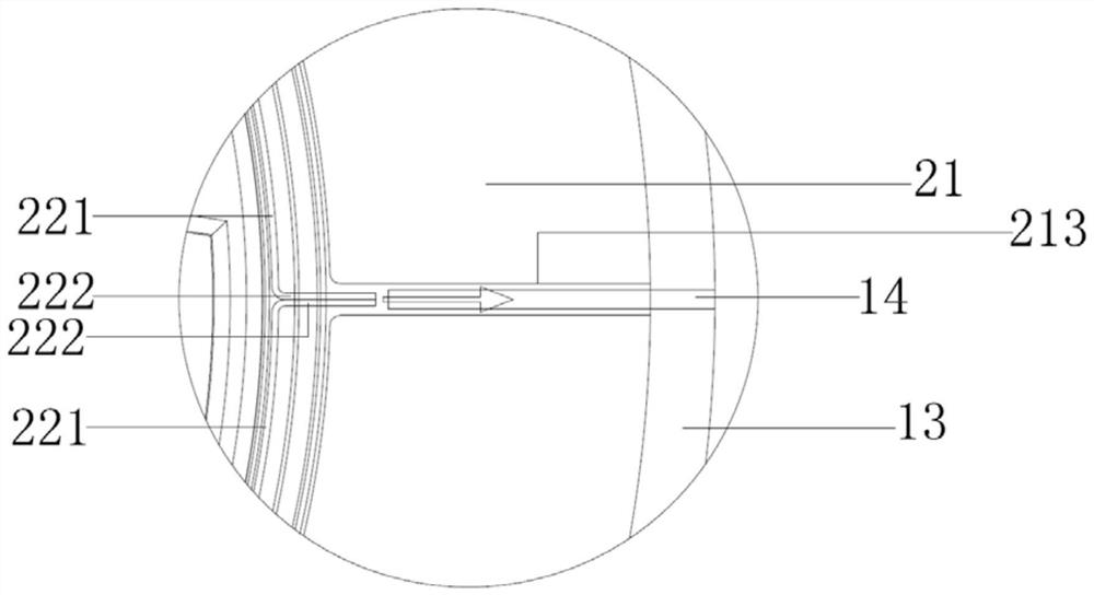
[0029] see Figure 1 to Figure 4 , the figure shows a wire reel with a wire take-up speed slowing mechanism provided by Embodiment 2 of the present invention. This embodiment further makes the following technical solutions as improvements on the basis of the above embodiments: The ring part 2 is formed by splicing two semicircular parts 22, and the joint of the two semicircular parts 22 extends outward to form a connecting part 221, and the connecting part 221 is fixedly connected to the brake part 21, specifically, the semicircular part 22 The ends of the two bent ends 222 are outwardly formed, and the two bent ends 222 are joined together to form a connecting part 221 .

[0030] Through the setting of the above structure, it is easy to install and disassemble the ring piece, and it is convenient for the brake component to pull the ring piece more evenly, so that it changes from a circle to an ellipse.

Embodiment 3

[0032] see Figure 1 to Figure 4 , the figure shows a wire reel with a wire take-up speed slowing mechanism provided by Embodiment 3 of the present invention. This embodiment further makes the following technical solutions as improvements on the basis of the above embodiments: The surface of the reel 1 is provided with a sliding cavity 13 for the sliding of the braking component 21, and the sliding cavity 13 is provided with sliding guide ribs 14 arranged radially along the reel 1, and the bottom of the braking component 21 is provided with a sliding connection. Slide groove 213 on the sliding guide rib 14. Through the setting of the above structure, the brake component can slide on a prescribed path, and the movement is more precise and stable.


PUM


Abstract

The invention provides a winder with a winding speed slowing mechanism. The winder comprises a winding reel and a deformable annular piece, wherein the winding reel is rotatably mounted on a winding support, and the winding support is provided with a support insert embedded in a central circular hole of the winding reel; and the deformable annular piece is installed in the central circular hole, at least one brake component is fixedly connected to the outer edge of the annular piece, the brake component is slidably connected to the surface of the winding reel at the same time, and the brake component slides back and forth in a radial direction of the winding reel and drives the annular piece to deform. Compared with the prior art, the safety and stability of the winder in use can be improved, and the service life of the whole winder is effectively prolonged.

Description

technical field [0001] The invention relates to a wire reel on electrical equipment, in particular to a wire reel with a wire take-up speed slowing mechanism. Background technique [0002] In electrical equipment such as vacuum cleaners, the power cord is generally stored by a cord reel. At present, the conventional design of the cord reel is to use the elastic force compressed by the coil spring to make the cord reel rotate, so as to achieve the winding effect of the power cord. [0003] However, this type of take-up method mainly has the following disadvantages: during the reset process, the inertia of the coil spring is getting bigger and bigger, resulting in faster and faster take-up speed, resulting in the swing of the power plug, which is easy to hurt the user or touch it. Other items, or even collide with the body and cause the power cord to fall off. Contents of the invention [0004] In view of this, the present invention provides a wire reel with a winding spee...

Claims


Application Information

Patent Timeline
Patent Type & Authority Applications(China)
IPC IPC(8): B65H75/44
CPCB65H75/4447B65H2701/34
Inventor 王佳文陈杰
Owner SUZHOU CHUNJU ELECTRIC CO LTD
Why Eureka
Try Eureka