
Movable balance weight lifting device, method and engineering machine for controlling device

A technology of movable counterweight and counterweight, which is applied in the direction of cranes, transportation and packaging, load hanging components, etc., and can solve the problem of movable counterweight drop

Inactive Publication Date: 2021-01-05
ZOOMLION HEAVY IND CO LTD
View PDF5 Cites 0 Cited by
  • Summary
  • Abstract
  • Description
  • Claims
  • Application Information

AI Technical Summary

Problems solved by technology

Therefore, during the long-term operation process, the movable counterweight will inevitably decline, and there is a risk of safety accidents

Method used


Image

  • Movable balance weight lifting device, method and engineering machine for controlling device
  • Movable balance weight lifting device, method and engineering machine for controlling device
  • Movable balance weight lifting device, method and engineering machine for controlling device

Examples


Embodiment Construction

[0033] Specific embodiments of the present invention will be described in detail below in conjunction with the accompanying drawings. It should be understood that the specific embodiments described here are only used to illustrate and explain the present invention, and are not intended to limit the present invention.

[0034] In the present invention, unless stated otherwise, the orientation words used are usually based on the orientation shown in the corresponding drawings.

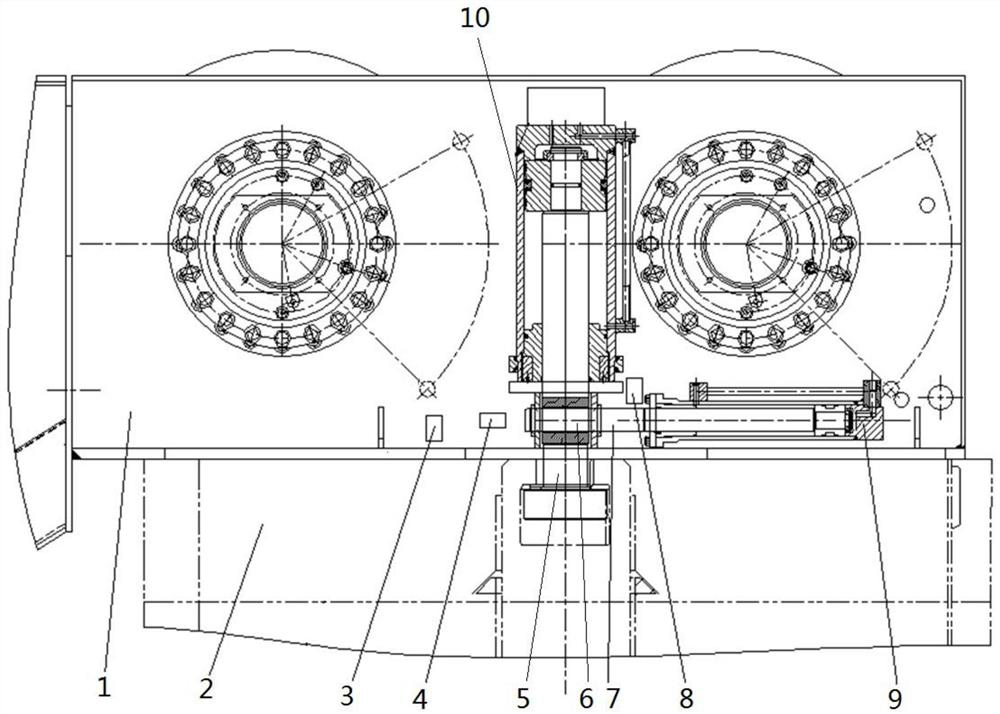
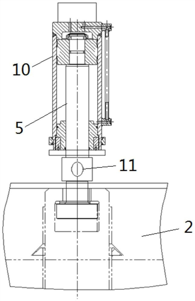
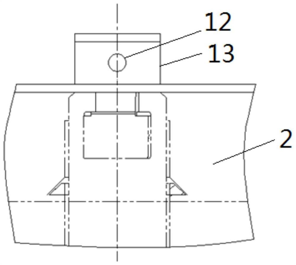
[0035] The first aspect of the present invention provides a movable counterweight lifting device, such as figure 1 As shown, the movable counterweight lifting device includes: a turntable 1; a lifting cylinder 10, the cylinder barrel of the lifting cylinder 10 is fixed on the turntable 1, and the lifting piston rod 5 of the lifting cylinder 10 is connected with the counterweight 2 , the lifting piston rod 5 is provided with a first through hole 11; a locking mechanism, the locking mechanism includes a s...


PUM


Abstract

The invention relates to the technical field of engineering equipment, and provides a movable balance weight lifting device, a method and engineering machine for controlling the device. The movable balance weight lifting device comprises a rotary table (1), a lifting oil cylinder (10) and a locking mechanism; a cylinder barrel of the lifting oil cylinder (10) is fixed to the rotary table, and a lifting piston rod (5) of the lifting oil cylinder is connected with a balance weight (2); a first through hole (11) is formed in the lifting piston rod; the locking mechanism comprises a safety pin (6), and the safety pin is provided with a locking position and an unlocking position, the locking position is inserted into the first through hole to lock the lifting piston rod after the balance weightis lifted to the designated position, and the unlocking position is separated from the first through hole to enable the lifting piston rod to drive the balance weight to move. According to the movable balance weight lifting device and the engineering machine, the lifting oil cylinder can be mechanically locked after the balance weight is lifted to the designated position, and the locking mode ismore reliable.

Description

technical field [0001] The invention relates to the technical field of engineering equipment, in particular to a movable counterweight lifting device, a method for controlling the device and construction machinery. Background technique [0002] At this stage, with the increase in the number of cranes in our country, the safety of crane operations has attracted more and more attention. Counterweight is an important part of wheeled construction machinery, especially large-tonnage cranes often use movable counterweights. When transferring, it is transported separately from the crane, and then lifted to the designated position by the lifting cylinder of the crane itself during operation. Usually, the cylinder barrel of the lifting cylinder is fixed on the turntable, and the movable counterweight moves up and down with the piston rod of the lifting cylinder to realize lifting and lowering. After the movable counterweight is lifted in place, the relative position between the pis...

Claims


Application Information

Patent Timeline
IPC IPC(8): B66C23/74B66C23/62B66C23/88B66C13/46B66C13/48
CPCB66C13/46B66C13/48B66C23/62B66C23/74B66C23/88
Inventor 谢俊陆阳陈吕永标沈昌武
Owner ZOOMLION HEAVY IND CO LTD
Learn More