A heat dissipation structure for power electronic components

A technology of heat dissipation structure and power electronics, which is applied in the direction of electrical components, electrical equipment structural parts, chemical instruments and methods, etc., and can solve the problems of high local temperature of components, accelerated aging, uneven heating, etc.

Active Publication Date: 2022-05-20
HUAINAN UNITED UNIVERSITY
View PDF40 Cites 0 Cited by
  • Summary
  • Abstract
  • Description
  • Claims
  • Application Information

AI Technical Summary

Problems solved by technology

[0003] With the development of society, the current electronic components are all modularized. Modular electronic component modules can be integrated on a circuit board, and when they are working, some modules are working, and some modules are in a dormant state. cause uneven heating
However, the current heat dissipation methods are uniform heat dissipation, and the phenomenon of high local temperature of the components has always existed, which cannot be solved well, and it will cause damage to the components or accelerate aging for a long time

Method used


Image

  • A heat dissipation structure for power electronic components
  • A heat dissipation structure for power electronic components
  • A heat dissipation structure for power electronic components

Examples


Embodiment Construction

[0031] The following will clearly and completely describe the technical solutions in the embodiments of the present invention with reference to the accompanying drawings in the embodiments of the present invention. Obviously, the described embodiments are only some, not all, embodiments of the present invention. Based on the embodiments of the present invention, all other embodiments obtained by persons of ordinary skill in the art without making creative efforts belong to the protection scope of the present invention.

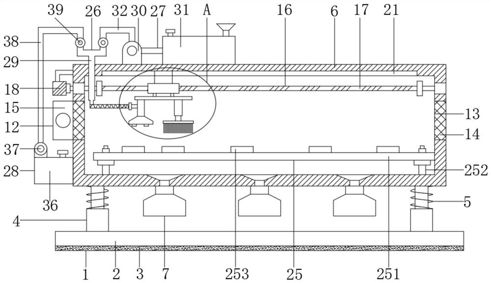
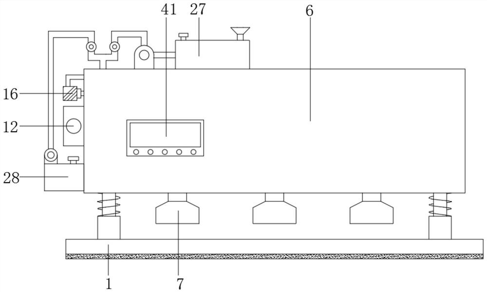
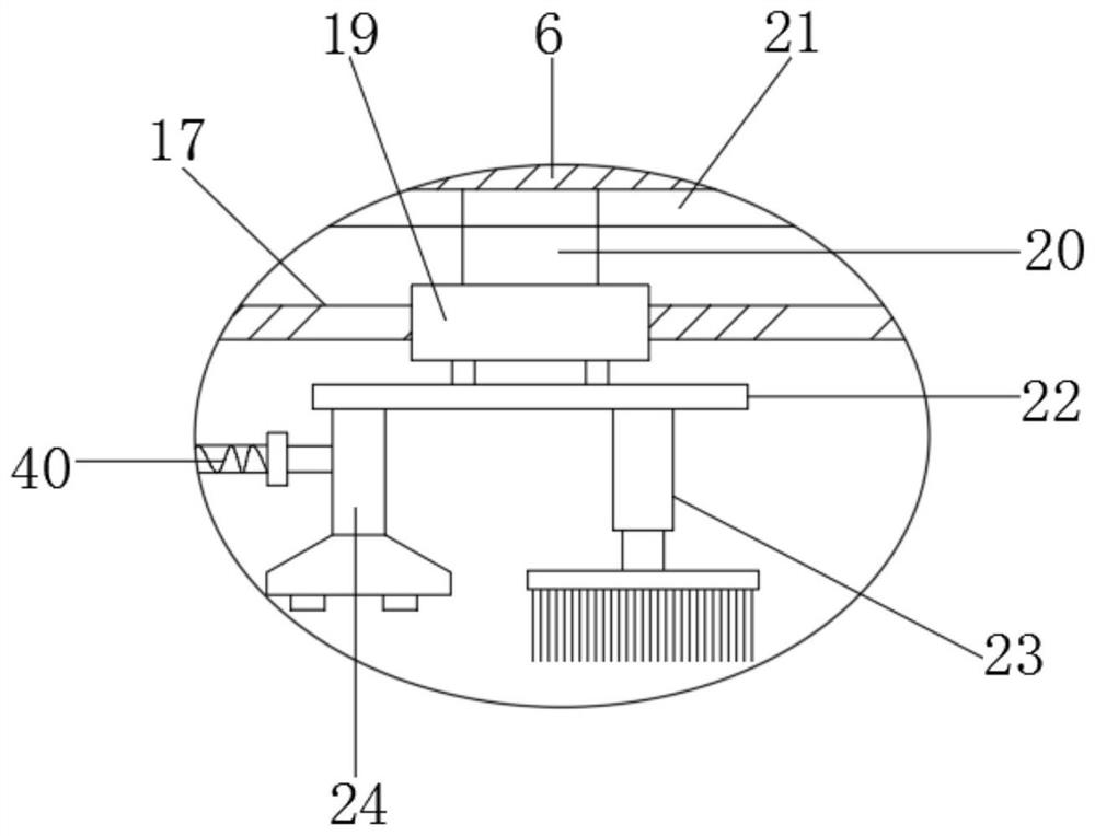
[0032] see Figure 1-7 , in an embodiment of the present invention, a heat dissipation structure for power electronic components includes a base 1, a box 6 is installed above the base, and the base 1 includes a bottom plate 2, and the lower end of the bottom plate 2 is provided with an anti-skid pad 3, and the bottom of the bottom plate 2 Buffer columns 4 are arranged on the left and right sides of the upper end, the buffer columns 4 are set as elastic columns...


PUM


Abstract

The invention discloses a heat dissipation structure for power electronic components, which comprises a base, a box body is mounted on the top of the base, a plurality of collectors are distributed at the lower end of the box body, the left and right side walls of the box body are provided with heat dissipation mechanisms, and the top of the box body is provided with a heat dissipation mechanism. There is a moving mechanism, a mounting plate is arranged under the moving mechanism, a cleaning mechanism is arranged on one side of the lower end of the mounting plate, and a fixed-point blowing mechanism is arranged on the other side; the outer side of the box is provided with an auxiliary mechanism, and the auxiliary mechanism includes a cold air mechanism, a flushing mechanism, and a cleaning mechanism. Mechanism and tee pipe, the tee pipe is arranged on the top left side of the box body, and the lower end of the tee pipe is located in the box body, and the bottom of the tee pipe is connected to the fixed-point blowing mechanism through an elastic hose. In the present invention, the moving mechanism and the fixed-point blowing mechanism can conduct a fixed-point inspection of the temperature of the component body, and when a local high temperature occurs, the cooling mechanism cooperates with the fixed-point blowing mechanism to achieve local rapid cooling, avoiding local heat dissipation. Excessive temperature damage to components.

Description

technical field [0001] The invention relates to the technical field of electronic power, in particular to a heat dissipation structure of power electronic components. Background technique [0002] Electronic components are components of electronic components and small electrical machines and instruments. They are often composed of several parts and can be used in similar products; they often refer to certain parts in industries such as electrical appliances, radios, and instruments, such as capacitors and transistors. The general term for sub-devices such as hairsprings, springs, etc., common ones are diodes, etc. Since the invention and creation of electronic components, they have been used more and more in modern industry and modern life. For modern industries, especially mining, chemical industry, Electric power, industrial manufacturing and other fields. [0003] With the development of society, the current electronic components are all modularized. Modular electronic c...

Claims


Application Information

Patent Timeline
Patent Type & Authority Patents(China)
IPC IPC(8): H05K7/20B08B5/02
CPCH05K7/20209H05K7/20172B08B5/02
Inventor 陆月朋戚琦
Owner HUAINAN UNITED UNIVERSITY
Why Eureka
Try Eureka