A UAV control method that meets the autonomous landing requirements of maneuvering platforms

A technology of unmanned aerial vehicle and multi-rotor unmanned aerial vehicle, which is applied in the field of unmanned aerial vehicle control to meet the autonomous landing requirements of mobile platforms. The effect of smooth trajectory, faster and more stable landing

Active Publication Date: 2022-04-05
BEIJING INSTITUTE OF TECHNOLOGYGY +1
View PDF16 Cites 0 Cited by
  • Summary
  • Abstract
  • Description
  • Claims
  • Application Information

AI Technical Summary

Problems solved by technology

In addition, although the PID algorithm is a control algorithm based on deviation, its parameters are mostly adjusted through experiments and manual debugging in practical engineering applications, which will lead to design results that are not globally optimal. From this perspective, it In fact, it is very dependent on the dynamic model of the controlled object, because once the mathematical model is obtained, better parameters can be found through theoretical design, which also becomes a factor that restricts the actual control efficiency and control accuracy of the algorithm.

Method used


Image

  • A UAV control method that meets the autonomous landing requirements of maneuvering platforms
  • A UAV control method that meets the autonomous landing requirements of maneuvering platforms
  • A UAV control method that meets the autonomous landing requirements of maneuvering platforms

Examples


Embodiment 1

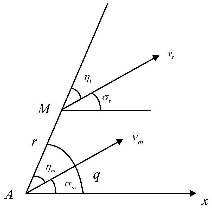
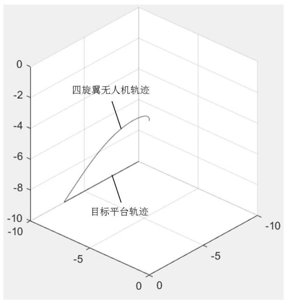
[0119] Assume that the trajectory of the target platform is a straight line, the initial point is at the origin, and the target platform moves in a straight line at a speed of 2m / s. The initial speed of the quadrotor UAV is 0, and it hovers at the coordinate point (10m, 20m, 10m),

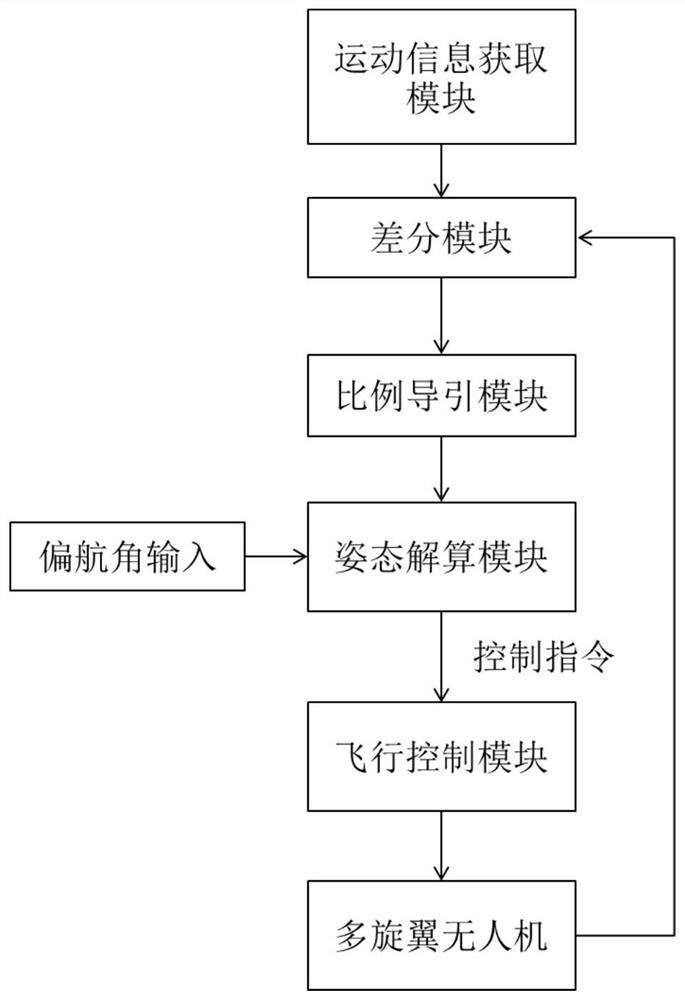
[0120] Input the position and movement information into the built simulation model to simulate the trajectory of autonomous landing. Among them, the proportional guidance coefficient k is 4, and the yaw angle of the quadrotor UAV is set to 30°.

[0121] The trajectory simulation of the target platform and the quadrotor UAV is as follows: image 3 shown, from image 3 It can be seen from the figure that the quadrotor UAV can land autonomously, and the landing trajectory is relatively smooth, with a large degree of curvature at the initial stage and a small degree of curvature at the end.

[0122] In addition, observe and analyze some control quantities in the output process, such as Figure 4 Sh...

Embodiment 2

[0125] The simulation experiment of the autonomous landing trajectory is carried out on the complex motion of the target platform. Assuming that the target platform moves according to the sinusoidal trajectory, the simulation experiment diagram of the target platform and the motion trajectory curve of the quadrotor UAV is as follows: Figure 7 shown.

[0126] From Figure 7 It can be seen from the figure that the quadrotor UAV can successfully land smoothly after the target mobile platform moves for two periods T, and the tracking effect in the process is better. , the curvature of the trajectory of the four-rotor in the initial stage is relatively large, that is, it is followed by turning with a large normal overload. The state of motion landed on the platform.

[0127] Based on the results of the above simulation experiments, a control algorithm proposed by the present invention that meets the requirements of autonomous landing is feasible.


PUM


Abstract

The invention discloses an unmanned aerial vehicle control system and a control method that meet the autonomous landing requirements of a mobile platform. Calculate the relative motion information of the target platform and the UAV; the proportional guidance module is used to obtain the three-axis overload of the UAV according to the relative position information; the attitude calculation module is used to obtain the UAV according to the three-axis overload The expected attitude quantity; the flight control module controls the flight attitude of the UAV according to the expected attitude quantity, so as to realize the autonomous landing of the UAV on the maneuvering platform. The control system and method provided by the present invention adopt a proportional guidance algorithm, so that the three-axis overload change and speed change are stable during the autonomous landing process of the UAV, and the landing trajectory is smooth, and the target platform can be quickly and accurately tracked to realize accurate autonomous landing.

Description

technical field [0001] The invention relates to the technical field of unmanned aerial vehicle control, in particular to an unmanned aerial vehicle control method that meets the autonomous landing requirements of a mobile platform. Background technique [0002] Due to its advantages of convenient use, flexible maneuverability, and high control precision, multi-rotor UAVs are widely used in the fields of emergency rescue and relief, material transportation, military strikes, etc. The landing of UAVs is a stage with high risk of mission execution. Autonomous landing on a maneuvering platform is of great significance for saving manpower and material resources and improving safety. [0003] At present, the autonomous landing of multi-rotor UAVs mostly adopts the traditional PID control algorithm, which realizes stable and accurate control by performing proportional integral differential processing on the deviation of position and speed information. The gyroplane flies to the de...

Claims


Application Information

Patent Timeline
Patent Type & Authority Patents(China)
IPC IPC(8): G05D1/08G05D1/12
CPCG05D1/12G05D1/0825
Inventor 林德福郭凯阳王江宋韬曹先彬王伟莫雳张福彪
Owner BEIJING INSTITUTE OF TECHNOLOGYGY
Why Eureka
Try Eureka