
Tyre tread comprising wavy grooves and sipes

A tire tread and tread technology, applied in the field of tread patterns, can solve problems such as increasing the driving cost per unit driving distance and the like

Active Publication Date: 2021-01-08
MICHELIN & CO CIE GEN DES ESTAB MICHELIN
View PDF20 Cites 0 Cited by
  • Summary
  • Abstract
  • Description
  • Claims
  • Application Information

AI Technical Summary

Problems solved by technology

This uneven wear can lead to premature removal of the tire from the vehicle in order to replace it with a brand new tire, which significantly increases the cost of driving per unit of distance traveled

Method used


Image

  • Tyre tread comprising wavy grooves and sipes
  • Tyre tread comprising wavy grooves and sipes
  • Tyre tread comprising wavy grooves and sipes

Examples


Embodiment Construction

[0052] In order to make the figures easier to understand, different variants of the invention may be described using the same reference numerals, wherein these reference numerals refer to the same kind of elements, both structurally and functionally.

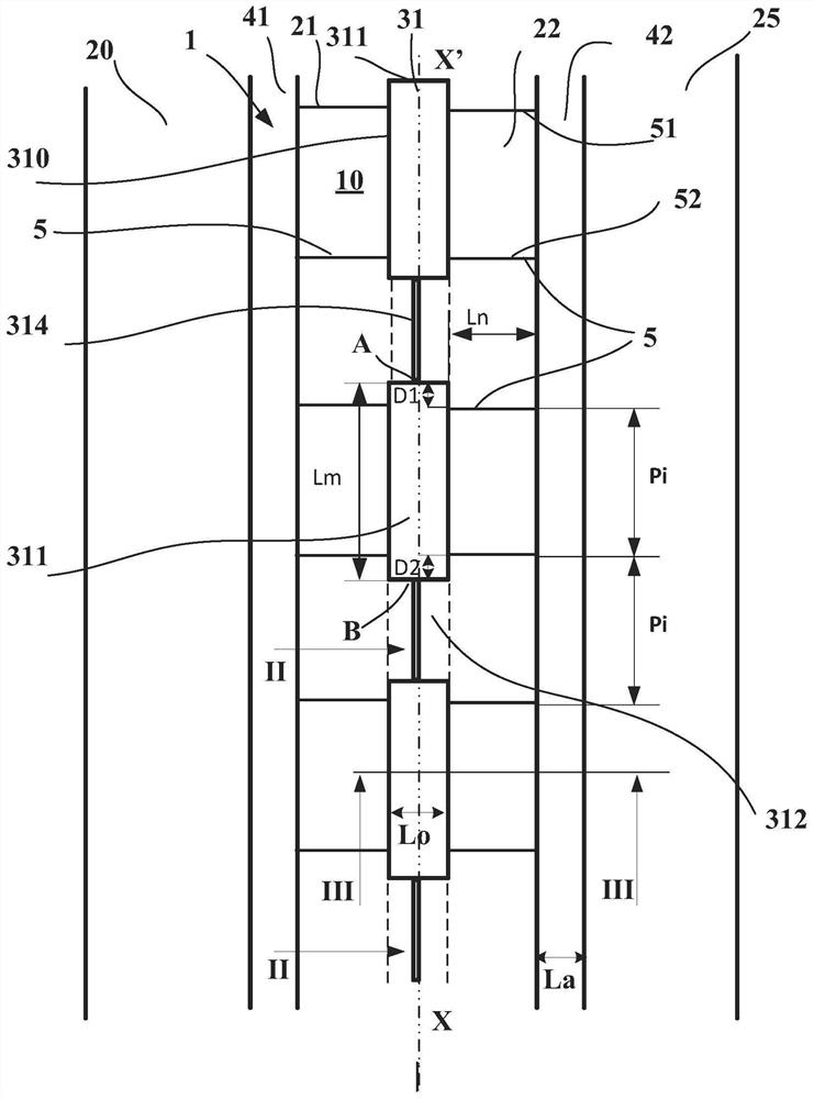
[0053] refer to figure 1 , a first variant of the invention describes a tread 1 having a tread surface 10 intended to come into contact with the road surface when the tire provided with said tread is running. This tread 1 has a thickness of material to be worn during running, in which thickness cuts, grooves or sipe are formed.

[0054] figure 1 A view is shown of the tread surface 10 of the tread comprising three circumferentially oriented grooves 31, 41, 42 (running in the circumferential direction indicated by the line XX'). These three grooves delimit two central circumferential ribs 21 , 22 and two edge ribs 20 , 25 located axially on the outside. These two grooves 41 , 42 are cuts open over the entire length of the groo...


PUM


Abstract

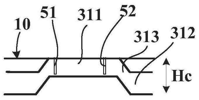
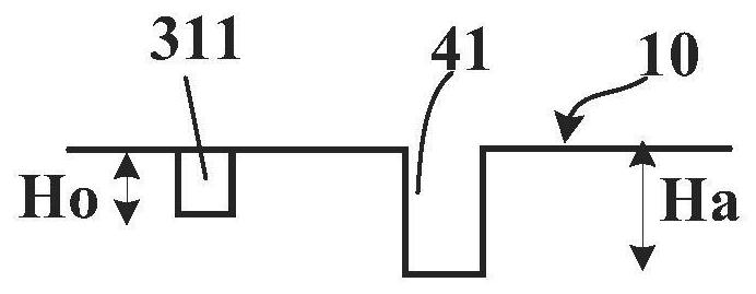
The invention relates to a tread (1) comprising at least two longitudinally oriented grooves (31, 41, 42), of which at least one wavy groove (31) opens onto the tread surface (10) of the tread, at least one rib (21) oriented in the longitudinal direction of the tread being delimited by at least one of said wavy grooves, each wavy groove (31) comprising external cavities (311) that are open onto the tread surface and internal cavities (312) that are hidden in the thickness of the tread, the external cavities (311) of each wavy groove (31) opening onto the tread surface (10) in the new state with a contour (310) of which the end points A and B that are furthest apart are at a distance Lm, the rib (21) of width Ln comprising a plurality of transverse sipes (5) located at a mean spacing Pi, this tread being such that: - the length Lm of the contour (310) of the external cavity (311) is equal to or greater than an integer multiple N of the spacing Pi by a quantity at most equal to 25% of this integer multiple N of the spacing Pi, - in the new state, N+1 transverse sipes (5) of one and the same rib (21) lead into each open cavity (311) bordering said groove, one of these transverse sipes(51) opening out close to the end point A of the contour (310) at a distance D1 from this point A, another transverse sipe (52) opening out close to the other end point B of the contour (310) at a distance D2 from this point B, the difference between the two distances D1 and D2 being at most equal to 5 mm.

Description

technical field [0001] The present invention relates to tire treads, and more particularly to tread patterns for such treads, which treads are more durable in terms of drainage in rainy weather, which treads also have improved wear properties; the invention also relates to treads provided with such Tread tires. Background technique [0002] In a known manner, the conditions under which heavily loaded vehicles are driven in rainy weather require the rapid removal of any water that may be present in the area where the tire (more specifically the tire tread) comes into contact with the road surface, so as to ensure that the material from which the tread is made is indeed compatible with the road surface. The road surface is in contact. Water that is not pushed away at the front and sides of the tire runs or partially collects in cuts or voids formed in the tire tread. [0003] The flow network formed by these cuts or voids needs to be durable, that is to say, be able to remai...

Claims


Application Information

Patent Timeline
Patent Type & Authority Applications(China)
IPC IPC(8): B60C11/04B60C11/12B60C11/03B60C11/13
CPCB60C11/0323B60C11/033B60C11/042B60C11/1236B60C11/1259B60C11/1281B60C2011/1361B60C2200/06B60C2011/0341
Inventor R·伯蒂埃F·马里尔T·齐夫科维奇
Owner MICHELIN & CO CIE GEN DES ESTAB MICHELIN
Learn More