
Combined supporting structure of fin actuating mechanism

A technology of an actuator and a supporting structure, which is applied in the direction of using hydrofoils to act on the surrounding water surface to reduce the movement of ships, which can solve the problems of increased maintenance workload, uncoordinated structural solutions, increased size and weight, etc., and achieves production costs and usage expenses. Lowering, improved installation and maintenance conditions, reduced size and weight

Active Publication Date: 2012-03-14
704TH RES INST OF CHINA SHIPBUILDING IND CORP
View PDF4 Cites 0 Cited by
  • Summary
  • Abstract
  • Description
  • Claims
  • Application Information

AI Technical Summary

Problems solved by technology

[0003] 1. The size and weight of the fin stabilizer actuator are too large - the outer diameter of the standard large-sized tapered roller bearing is relatively large. For example, taking the supporting shaft diameter Φ670mm actuator as an example, the outer diameter of the large-sized standard double-row tapered roller bearing The diameter is 1090mm, if the crosshead and the fin box are designed according to this size, the distance between the upper and lower plates of the fin box will reach 2000mm, and the size and weight of the actuator will increase significantly, which is technically or economically unacceptable to users. uncoordinated structural scheme;
[0004] 2. Complicated structure - due to the increase of the outer diameter of the bearing, the sealing between the bearing and the inner cavity of the crosshead body, and the sealing between the bearing and the seawater outside the outboard will bring more problems, and a more structured structure must be adopted. complex sealing;
[0005] 3. Inconvenient maintenance - large-scale rolling bearings are cumbersome to lubricate with grease, which increases the maintenance workload, and the small bearings at the end of the fin shaft are lubricated with oil stored in the inner cavity of the crosshead body, which will cause trouble in oiling;
[0006] 4. Combining the above factors, the production and use costs of the fin stabilizer actuator will increase significantly

Method used


Image

  • Combined supporting structure of fin actuating mechanism
  • Combined supporting structure of fin actuating mechanism
  • Combined supporting structure of fin actuating mechanism

Examples


Embodiment Construction

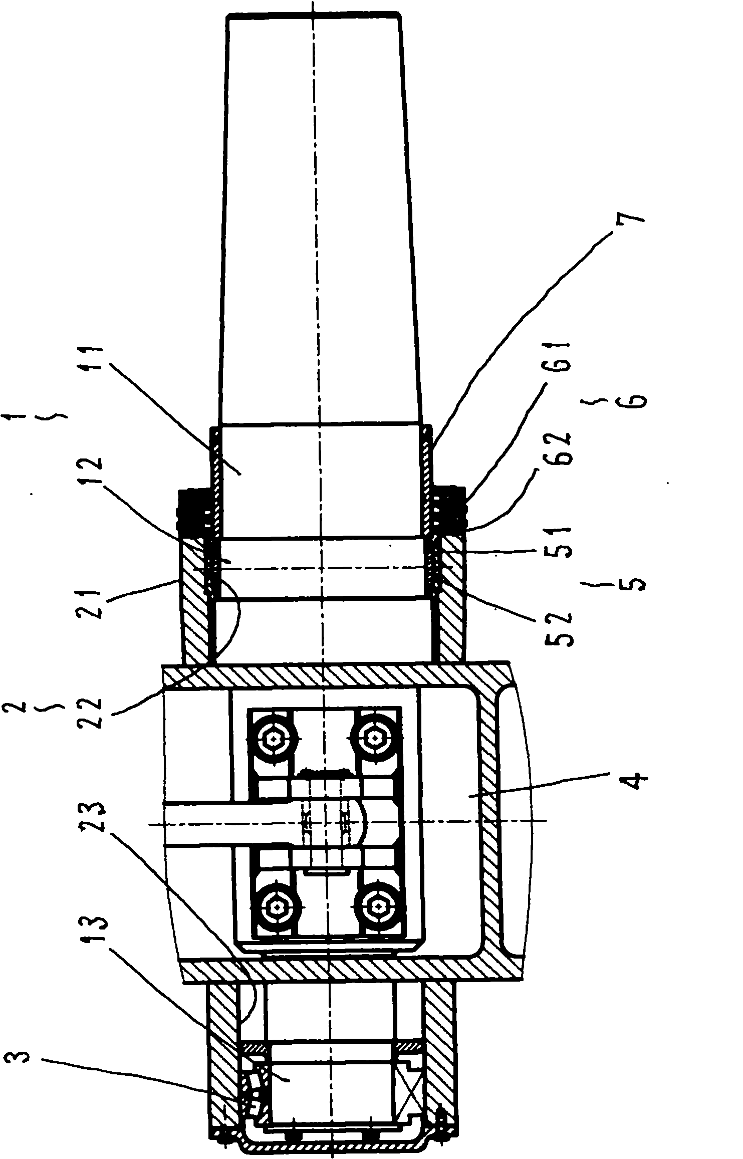
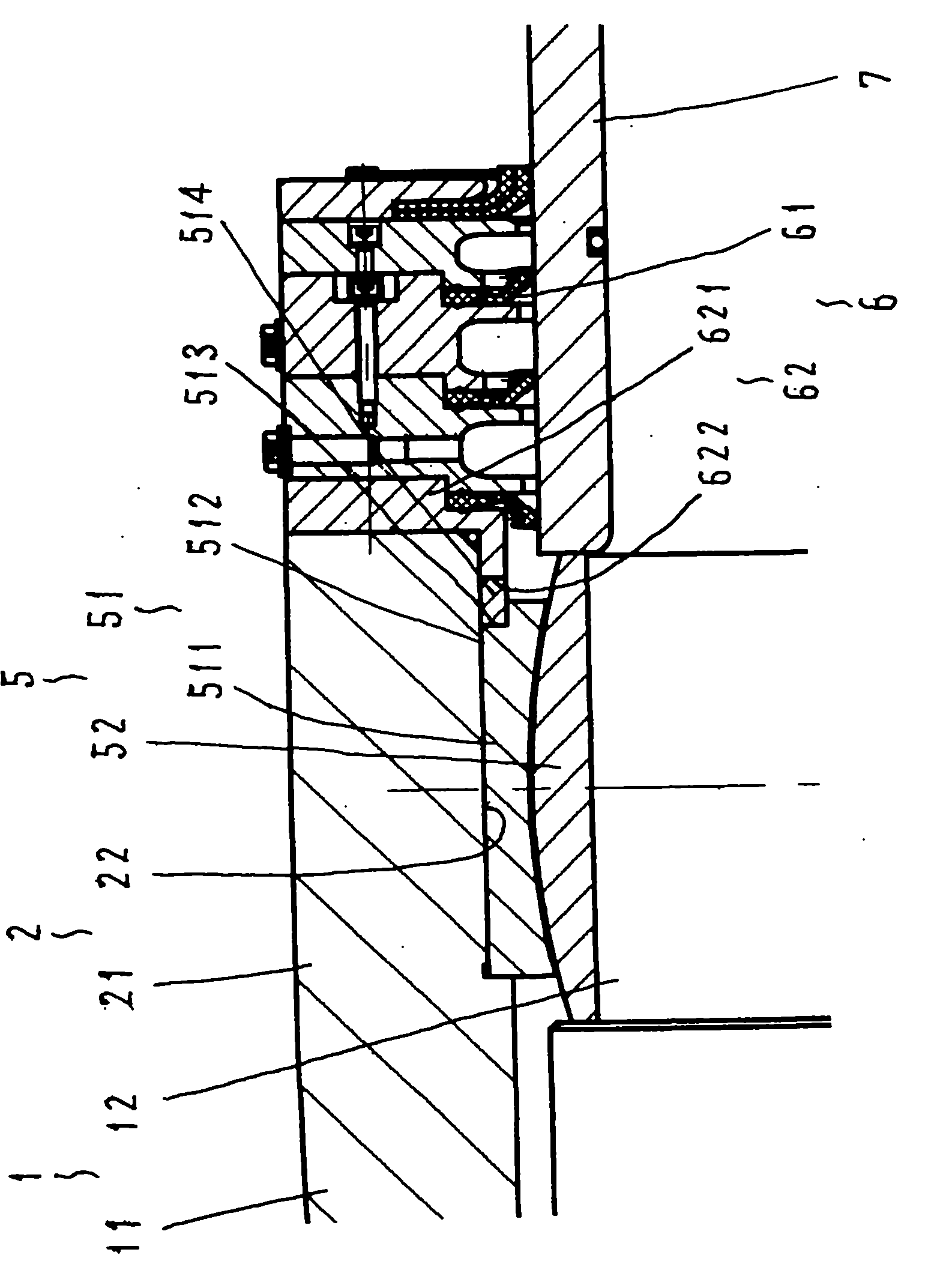
[0016] refer to figure 1 , the fin actuator combined support structure includes a fin shaft 1, a support 2, a double-row tapered roller bearing 3, a crosshead box 4, a radial joint bearing 5, a sealing assembly 6 and a shaft sleeve 7, wherein:

[0017] Fin shaft 1, its structure is the same or similar to the prior art, including shaft body 11, outer support section 12, inner support section 13, radial joint bearing 5 is arranged on the outer support section 12, and inner support section 13 is provided with Double row tapered roller bearings3.

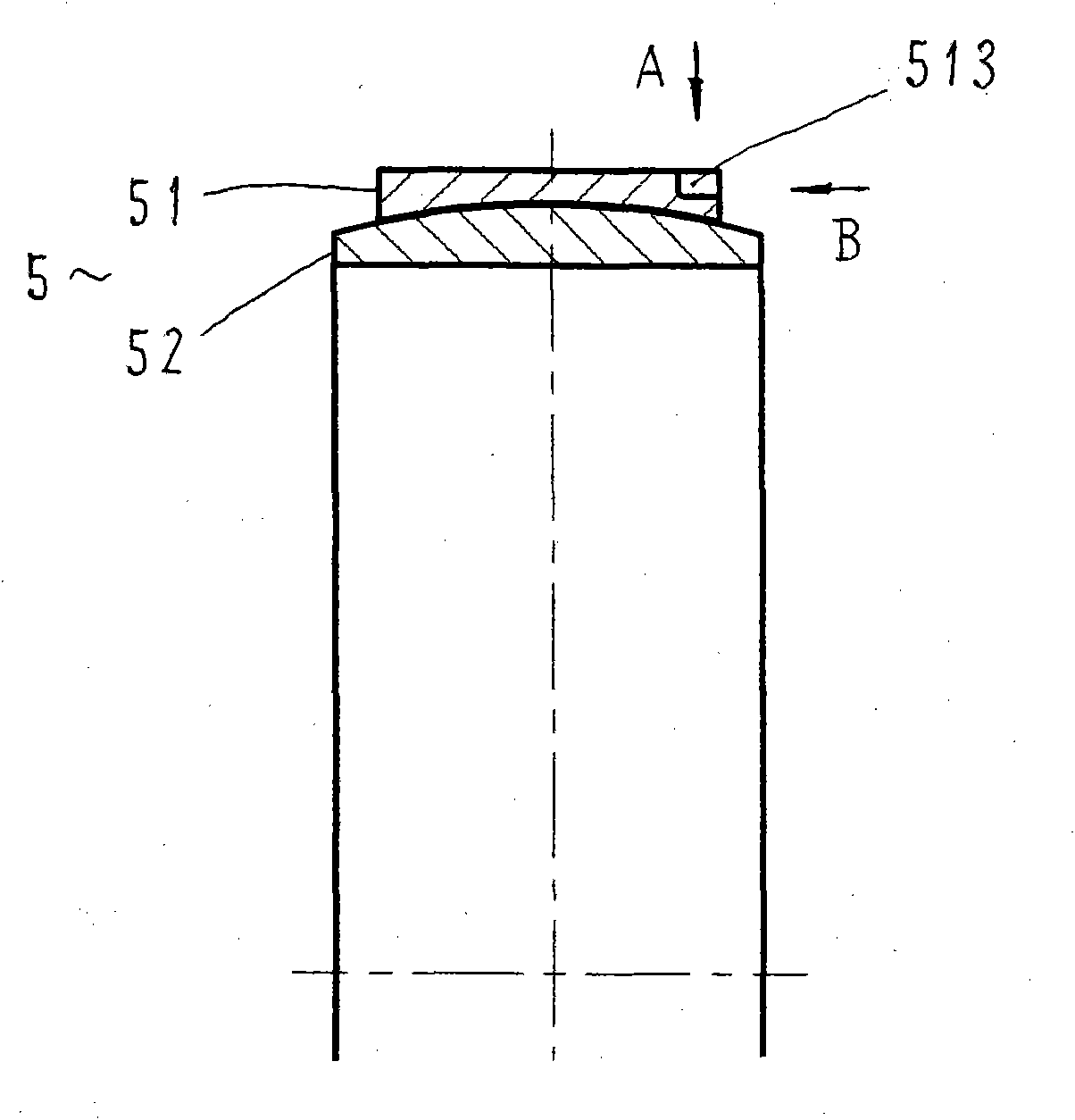
[0018] The support 2 has the same or similar structure as the prior art, and a radial spherical plain bearing 5 is installed in the outer bearing hole 22 of the outer base body 11, and the outer bearing hole 22 and the outer ring 51 of the radial spherical plain bearing 5 are in dynamic fit , so that the installation operation of the radial joint bearing 5 on the support 2 is greatly simplified. Compared with the tight fit of the rolli...


PUM


Abstract

A combined supporting structure of a fin actuating mechanism mainly solves the problems of improving the supporting performance and reducing the dimension and the weight of the mechanism and the like. The supporting structure adopts the technical scheme that a centripetal knuckle bearing is arranged on an outer supporting section of a fin shaft body to form the combined supporting structure of the knuckle bearing of the fin actuating mechanism and a rolling bearing. The combined supporting structure is suitable for actuating mechanisms of various large-scale and ultra-large-scale anti-rolling fin devices.

Description

Technical field: [0001] The invention relates to a device for reducing the rolling motion of a ship, and in particular to a component of the device. Background technique: [0002] Fin stabilizers are widely used in various ships. The fin shaft and its support are important components in the actuator of this equipment. In order to adapt to the best working state of the fin, the actuator is arranged in an inclined state along the axis. At this time, the fin In addition to bearing the radial force generated by the hydrodynamic forces of the fins, the supporting parts of the shaft also need to bear the axial component of the combined gravity of the fin shaft group and the fins. In order to adapt to the characteristics of this force system, the small and medium-sized fin stabilizer In the actuator, the support method of double rolling bearing is widely used, that is, the structure composed of two double-row tapered roller bearings. This type of bearing can not only bear radial an...

Claims


Application Information

Patent Timeline
Patent Type & Authority Applications(China)
IPC IPC(8): B63B39/06
Inventor 徐军郑敏祥洪超
Owner 704TH RES INST OF CHINA SHIPBUILDING IND CORP
Learn More