


Quick Research
Generate reliable direction feasibility study reports for your R&D in just a few steps.

Technical Q&A
Discover and master advanced knowledge NOW. Basics, ideas, possibilities, all at once.

Find Solutions
As an expert in R&D theories, this can generate solutions to your technical problems instantly.

Evaluate Feasibility
Analyze your overall solution with one click, know your potential R&D risks in advance.

Monitor Landscape
Get weekly tech updates, stay abreast of the latest tech innovations and key insights.
Bonded structure of endoscope
A technology for endoscopes and adhesives, applied in the fields of endoscopes, telescopes, medical science, etc., can solve problems such as adhesive leakage
- Summary
- Abstract
- Description
- Claims
- Application Information
AI Technical Summary
Problems solved by technology
Method used
Image

Examples
no. 1 approach
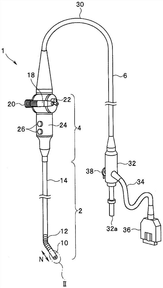
[0034] figure 1 It is a perspective view showing an outline of the structure of an endoscope having the adhesive structure of the present embodiment.
[0035] Such as figure 1 As shown, the main parts of the endoscope 1 include: an elongated insertion portion 2 that can be inserted into a subject; an operation portion 4 ; a universal cable 30 ; and a connector 32 .
[0036] The insertion part 2 includes a front end part 10, a bending part 12 and a rigid pipe part 14 in order from the front end side in the longitudinal direction N to form its main part, wherein the bending part 12 can be bent in multiple directions, and the pipe part 14 is for insertion. The part 2 is elongated in the longitudinal direction N. That is, the endoscope 1 of the present embodiment is constituted by a rigid endoscope having a hard insertion portion 2 .
[0037] The operation part 4 is connected to the root end of the pipe part 14 in the longitudinal direction N. A rotatable operating rod 18 and ...
no. 2 approach
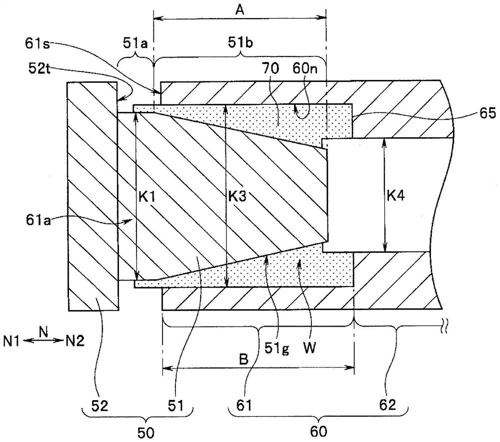
[0071] Figure 5 It is a partial cross-sectional view showing the outline of the bonding structure of the endoscope according to this embodiment.
[0072] The bonding structure of the endoscope of the second embodiment is the same as the above-mentioned Figure 1 ~ Figure 3 Compared with the adhesive structure of the endoscope of the first embodiment shown, the difference lies in that the second inner diameter portion of the cylindrical body is composed of a ring movable in the longitudinal direction, and the ring is moved in the longitudinal direction by the urging member. Front side push.
[0073] Therefore, only this point of difference will be described, and the same reference numerals will be assigned to the same components as those in the first embodiment, and description thereof will be omitted.
[0074] Such as Figure 5 As shown, in this embodiment, the second inner diameter portion 62 is formed as a ring 62d movable in the longitudinal direction N on the inner per...
no. 3 approach
[0082] Figure 6 It is a partial sectional view showing the outline of the bonding structure of the endoscope according to this embodiment, Figure 7 is along Figure 6 A cross-sectional view of the front end hard part of line VII-VII, Figure 8 is along Figure 6 A cross-sectional view of the cylindrical body on the line VIII-VIII.
[0083] The bonding structure of the endoscope of the third embodiment is the same as the above-mentioned Figure 1 ~ Figure 3 Compared with the bonding structure of the endoscope of the first embodiment shown, the difference lies in that: on the outer periphery of the embedded part of the front end hard member, there is formed along the longitudinal direction a hole that can be arranged on the inner periphery of the cylindrical body. Grooves into which protrusions fit.
[0084] Therefore, only this point of difference will be described, and the same reference numerals will be assigned to the same components as those in the first embodiment, ...
PUM
 Abstract
Description
Claims
Application Information
 - R&D Engineer
- R&D Manager
- IP Professional
- Industry Leading Data Capabilities
- Powerful AI technology
- Patent DNA Extraction
Browse by: Latest US Patents, China's latest patents, Technical Efficacy Thesaurus, Application Domain, Technology Topic, Popular Technical Reports.
© 2024 PatSnap. All rights reserved.Legal|Privacy policy|Modern Slavery Act Transparency Statement|Sitemap|About US| Contact US: help@patsnap.com