Rotary spiral dispensing valve

A dispensing valve and screw-type technology, applied in the field of dispensing valves, can solve problems such as inability to dispensing glue, and achieve the effects of improving glue performance, improving work efficiency, and quickly installing and connecting

Pending Publication Date: 2021-01-12
苏州海汰池自动化科技有限公司
View PDF0 Cites 0 Cited by
  • Summary
  • Abstract
  • Description
  • Claims
  • Application Information

AI Technical Summary

Problems solved by technology

[0004] The purpose of the present invention is to provide a rotary screw dispensing valve to solve the problem that two different glues cannot be mixed together for dispensing in the above background technology

Method used


Image

  • Rotary spiral dispensing valve
  • Rotary spiral dispensing valve
  • Rotary spiral dispensing valve

Examples


Embodiment Construction

[0020] The technical solutions in the embodiments of the present invention will be clearly and completely described below with reference to the accompanying drawings in the embodiments of the present invention. Obviously, the described embodiments are only a part of the embodiments of the present invention, but not all of the embodiments.

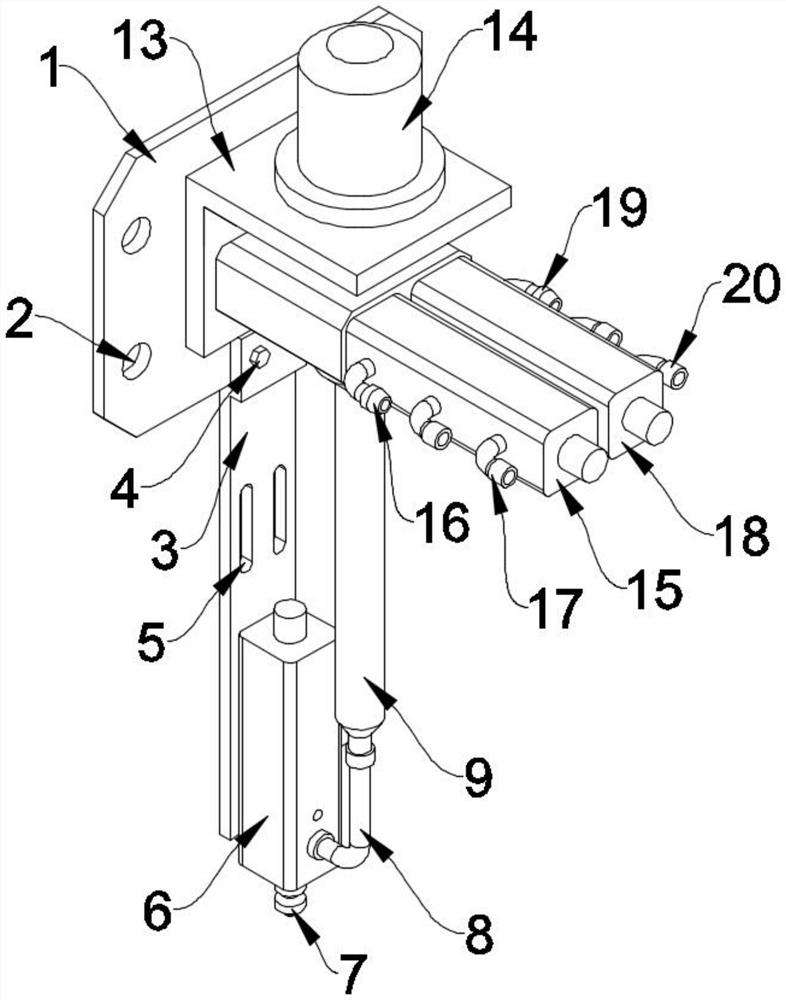
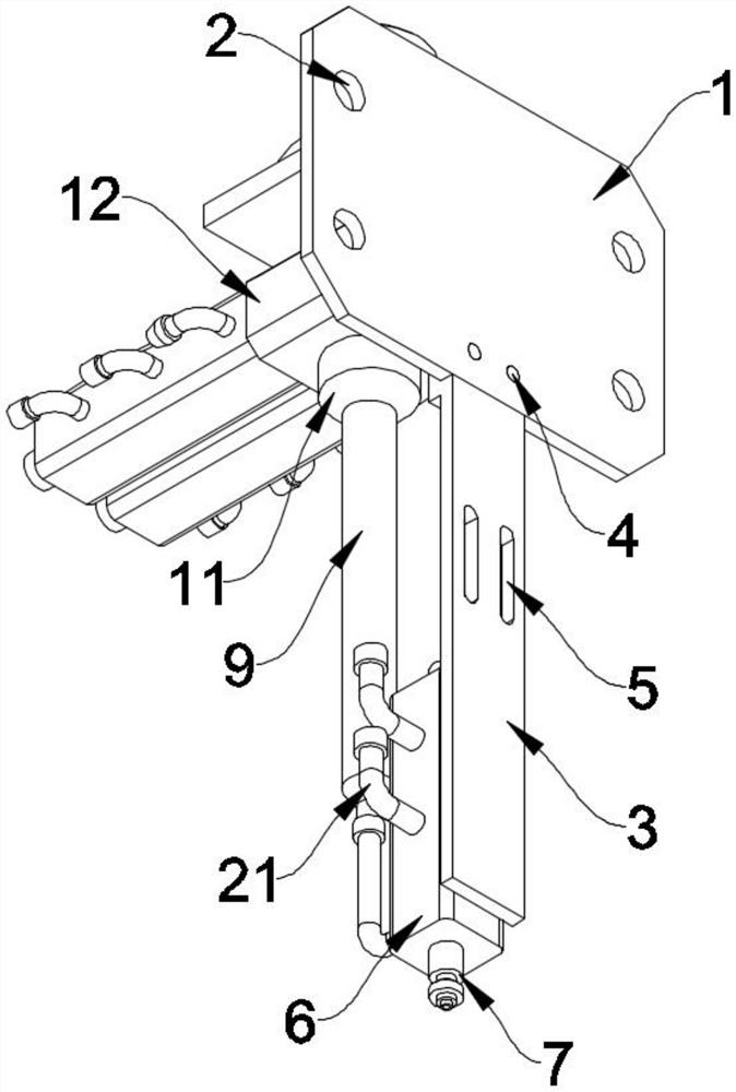
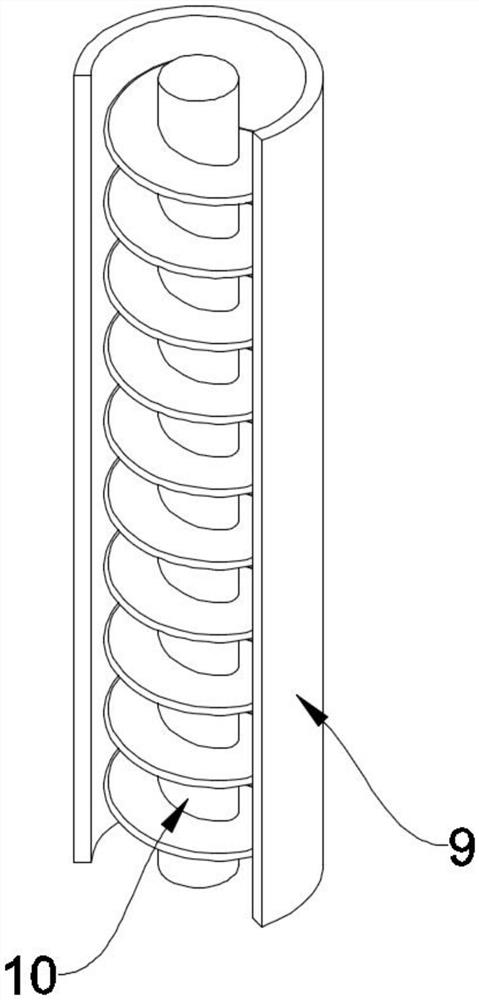
[0021] see Figure 1-4 , an embodiment provided by the present invention: a rotary screw type glue dispensing valve, including a spiral tube 9, a rotary screw rod 10 is arranged inside the spiral tube 9, a connecting sleeve 11 is arranged on the upper end of the spiral tube 9, and the spiral tube 9 The upper and lower ends of the spiral tube 9 are provided with threads, the connecting sleeve 11 and the spiral tube 9 are connected by threads, and the upper end of the connecting sleeve 11 is provided with a glue cavity box 12, and the glue cavity box 12 is fixedly connected with the connecting sleeve 11. The upper end of the rotating screw ro...


PUM


Abstract

The invention discloses a rotary spiral dispensing valve, relates to the related field of dispensing valves, and aims to solve the problem that two different types of glue cannot be mixed together fordispensing in the prior art. A rotary screw rod is arranged in a spiral pipe; a connecting sleeve is arranged at the upper end of the spiral pipe; the spiral pipe is in a circular pipe shape, and threads are arranged at the upper end and the lower end of the spiral pipe; the connecting sleeve is connected with the spiral pipe through thread; a glue cavity box is arranged at the upper end of the connecting sleeve, and the glue cavity box is fixedly connected with the connecting sleeve; a servo motor is arranged at the upper end of the rotary screw rod and connected with the rotary screw rod through a coupler; a first feeding pipe is arranged at the lower end of the spiral pipe and connected with the spiral pipe through threads; a first dispensing valve is arranged at the rear end of the first feeding pipe; and the first feeding pipe is in threaded connection with the first dispensing valve, and a glue outlet pipe is arranged at the lower end of the first dispensing valve.

Description

technical field [0001] The invention relates to the related field of glue dispensing valves, in particular to a rotary screw type glue dispensing valve. Background technique [0002] Dispensing valves are used in optics, optoelectronic industries, biochemical industries, etc., and the existing dispensing valves are divided into pneumatic and electric. Press into the feed pipe connected to the material cylinder chamber; back-suction dispensing valve: give a signal to the solenoid valve to drive the dispensing valve piston to move down, the glue will pass through the material cylinder, and the glue will be pressed out from the needle. Thimble-type dispensing valve: It moves in the opposite direction to the suction-type dispensing valve, and a signal is given to the solenoid valve to drive the dispensing valve piston to move upward, the glue will pass through the material cylinder, and the glue will be pressed out from the needle. The amount of glue dripped is determined by th...

Claims


Application Information

Patent Timeline
Patent Type & Authority Applications(China)
IPC IPC(8): B05C5/02B05C11/10B01F7/24
CPCB05C5/02B05C11/10B01F27/92
Inventor 刘凡
Owner 苏州海汰池自动化科技有限公司
Why Eureka
Try Eureka