A cantilevered robotic arm

A robotic arm and cantilever technology, applied in the direction of manipulators, manufacturing tools, etc., can solve the problems of inability to meet, reduce the overturning application of the robotic arm, and the difficulty of conveying oblique materials with the robotic arm.

Active Publication Date: 2021-11-05
ZHENJIANG RUIHAO ENG PLASTIC
View PDF7 Cites 0 Cited by
  • Summary
  • Abstract
  • Description
  • Claims
  • Application Information

AI Technical Summary

Problems solved by technology

[0003] Due to the limitations of the assembly structure in the actual application of the mechanical arm in the prior art, the turning application of the mechanical arm during the conveying process is greatly reduced, so that the mechanical arm has great difficulties in conveying oblique materials, so it cannot meet the existing requirements technology required

Method used


Image

  • A cantilevered robotic arm
  • A cantilevered robotic arm
  • A cantilevered robotic arm

Examples


Embodiment 1

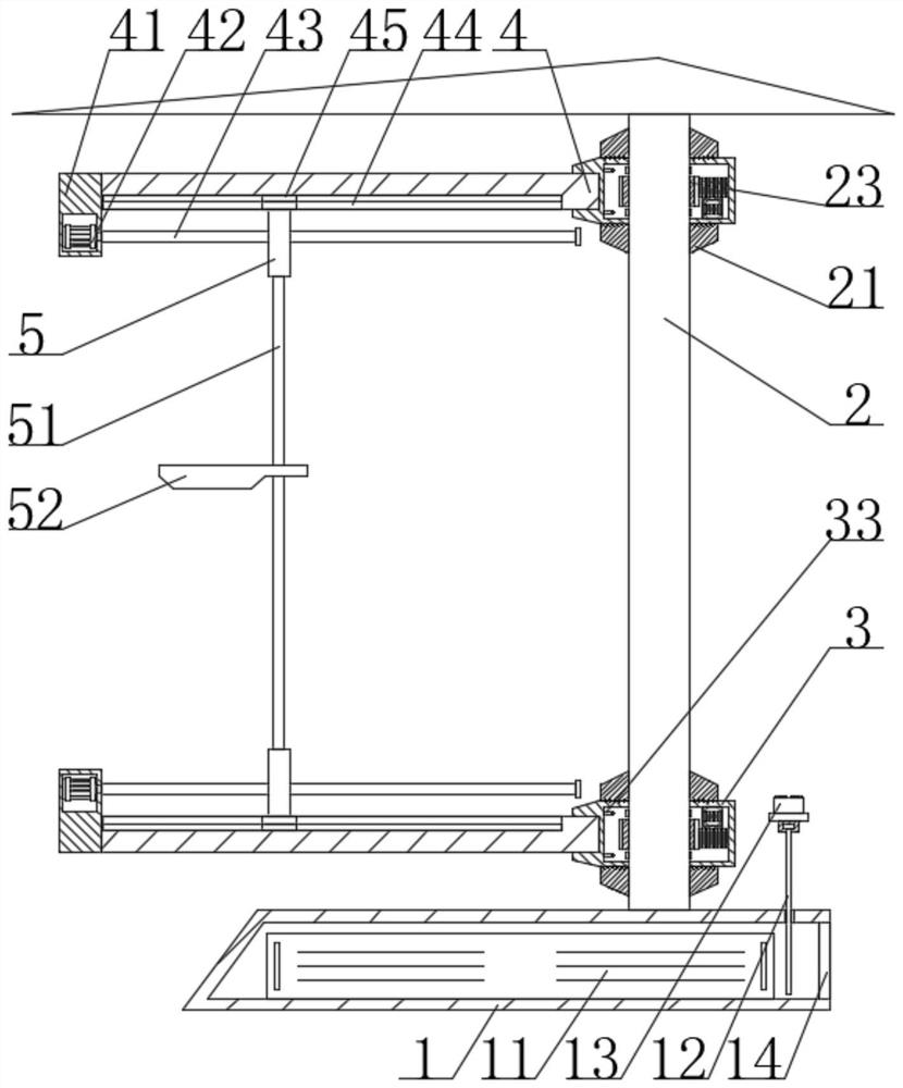
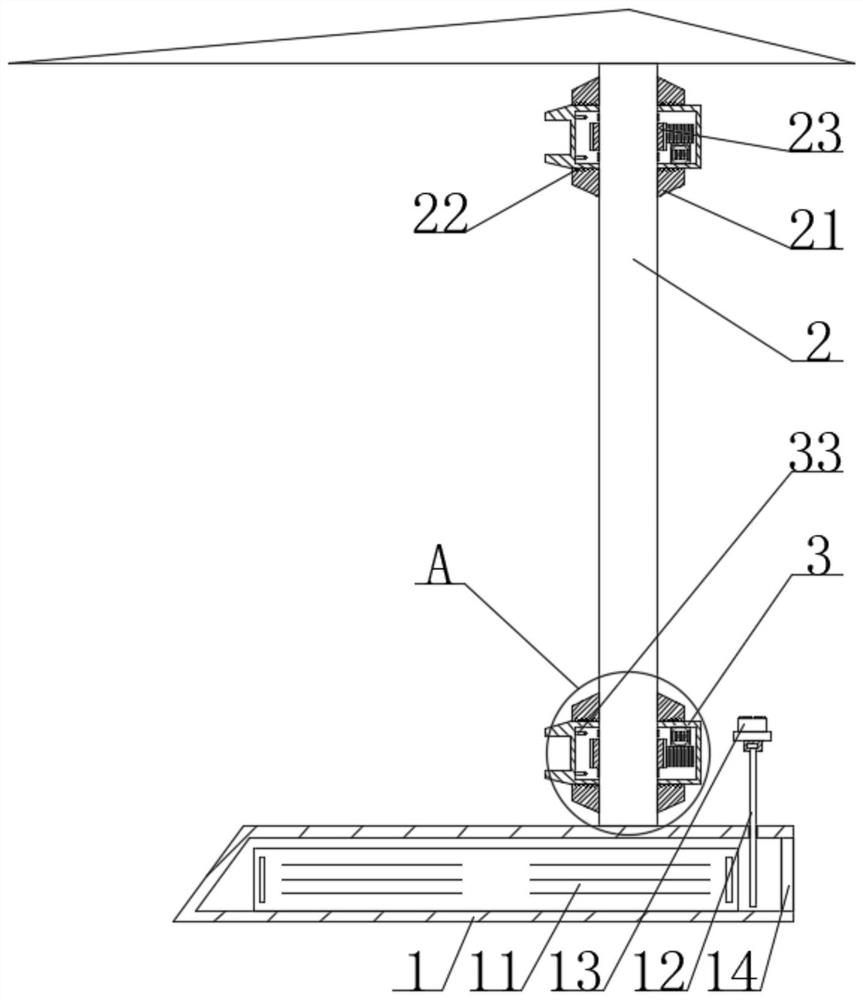
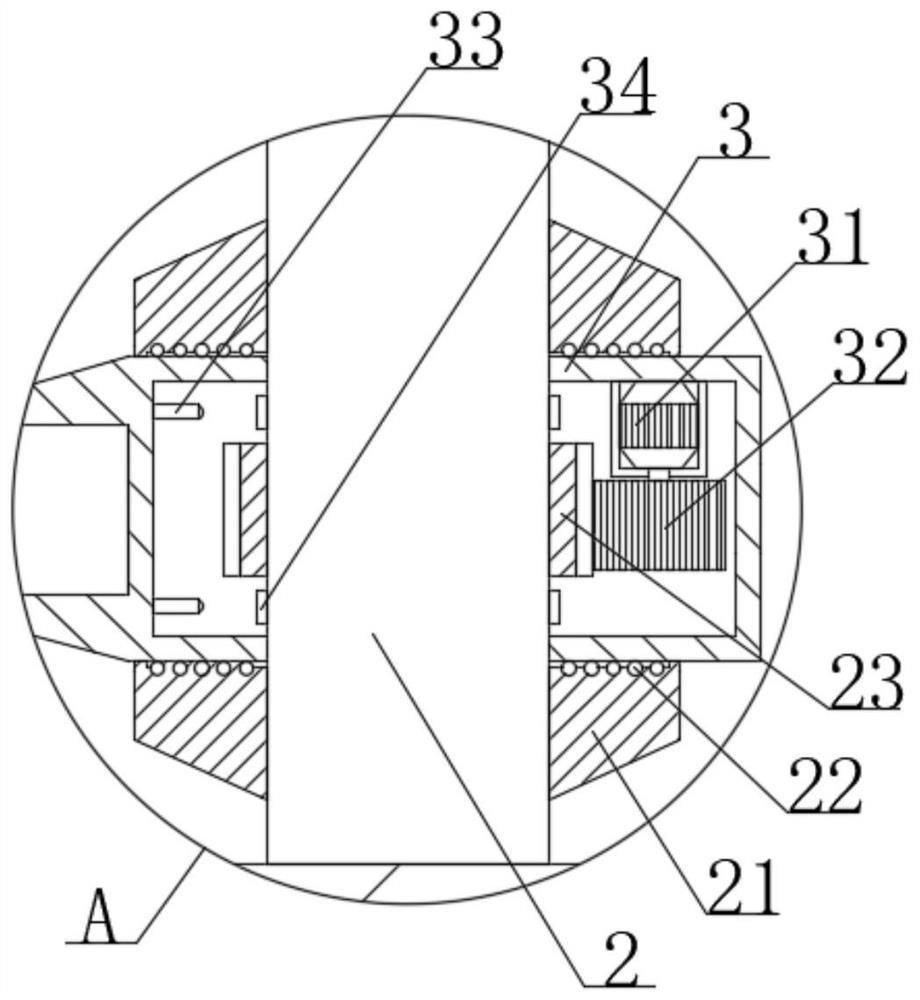
[0023] see Figure 1-5 , the present invention provides a technical solution: a cantilever mechanical arm, including a base 1, a support column 2 and a cantilever frame 4, the base 1 is in a right-angled trapezoidal structure, and the lower surface of the base 1 is provided with anti-slip lines, the base 1 The middle part of the lower surface of the inner wall is fixedly connected with a battery 11 by bolts, and the battery 11 can effectively provide electric energy. The middle part of the upper surface of the base 1 near the edge of one end is threadedly inserted with a screw rod 12, and the outer top of the screw rod 12 passes through a bearing The controller 13 is rotatably connected, and the position of the controller 13 on the base 1 can be effectively driven to lift through the screw rod 12, so as to facilitate the manipulation by users at different elevated positions. The middle part of one end of the base 1 is fixed and connected with a cover by bolts Plate 14, a seali...

Embodiment 2

[0025] see Figure 1-5, the present invention provides a technical solution: a cantilever mechanical arm, including a base 1, a support column 2 and a cantilever frame 4, the base 1 is in a right-angled trapezoidal structure, and the lower surface of the base 1 is provided with anti-slip lines, the base 1 The middle part of the lower surface of the inner wall is fixedly connected with a battery 11 by bolts, and the battery 11 can effectively provide electric energy. The middle part of the upper surface of the base 1 near the edge of one end is threadedly inserted with a screw rod 12, and the outer top of the screw rod 12 passes through a bearing The controller 13 is rotatably connected, and the position of the controller 13 on the base 1 can be effectively driven to lift through the screw rod 12, so as to facilitate the manipulation by users at different elevated positions. The middle part of one end of the base 1 is fixed and connected with a cover by bolts Plate 14, a sealin...


PUM


Abstract

The invention discloses a cantilever mechanical arm, which includes a base, a support column and a cantilever frame; the invention enables the mobile platform to effectively displace on the threaded assembly through the gear plate by starting the third motor through the controller, thereby effectively lifting the The position of the mobile platform on the three-dimensional surface is adjusted for displacement, and the two first motors are controlled in reverse by the controller to effectively cause the two cantilever frames to perform reverse displacement, so that the threaded components on the two connectors can implement the length The reorganization further promotes the folding of the mobile platform, which enables the user to be more flexible and changeable in actual operation and effectively adapts to the application in complex scenes. The slider provided in the chute on the cantilever frame can effectively limit the thread The components are always arranged vertically, which effectively limits the displacement transmission of the mobile platform on the three-dimensional surface and effectively satisfies the effect of multi-modal applications.

Description

technical field [0001] The invention relates to the technical field of mechanical arms, in particular to a cantilevered mechanical arm. Background technique [0002] The robotic arm is the most widely used automatic mechanical device in the field of robotics. It can be seen in the fields of industrial manufacturing, medical treatment, entertainment services, military, semiconductor manufacturing, and space exploration. There are differences, but they all have a common feature, that is, they can accept instructions and precisely locate to a certain point in three-dimensional (or two-dimensional) space for operation, while the cantilevered mechanical arms in the prior art are still not available in practical applications. There are many deficiencies, such as: [0003] Due to the limitations of the assembly structure in the actual application of the mechanical arm in the prior art, the turning application of the mechanical arm in the conveying process is greatly reduced, so th...

Claims


Application Information

Patent Timeline
Patent Type & Authority Patents(China)
IPC IPC(8): B25J11/00
CPCB25J11/00
Inventor 施正良王顶明
Owner ZHENJIANG RUIHAO ENG PLASTIC
Why Eureka
Try Eureka