
Tunnel piston pressure relief device

A pressure relief device and piston technology, applied in mining devices, tunnel systems, roads, etc., can solve problems such as train shaking, safety accidents, affecting train running, etc., and achieve the effect of reducing wind speed and good safety.

Inactive Publication Date: 2021-01-12
瞿启芳
View PDF0 Cites 0 Cited by
  • Summary
  • Abstract
  • Description
  • Claims
  • Application Information

AI Technical Summary

Problems solved by technology

[0005] In view of this, the present invention provides a tunnel piston in order to solve the problem that when a high-speed train enters a tunnel, the air vibration is more severe, which may cause the train to shake significantly, seriously affect the running of the train, and even cause safety accidents. pressure relief device

Method used


Image

  • Tunnel piston pressure relief device
  • Tunnel piston pressure relief device
  • Tunnel piston pressure relief device

Examples


Embodiment Construction

[0029] The following is further described in detail through specific implementation methods:

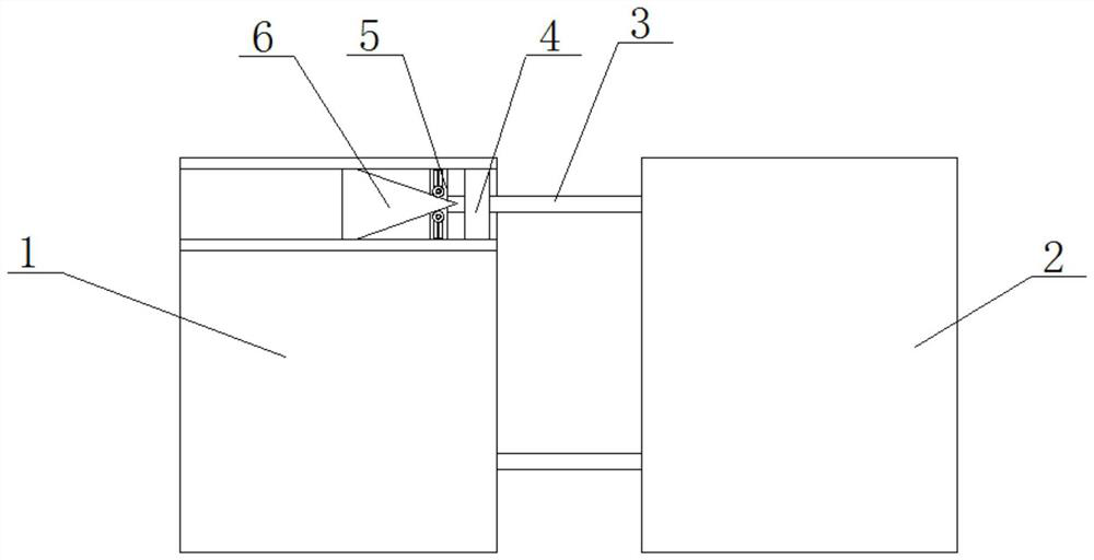
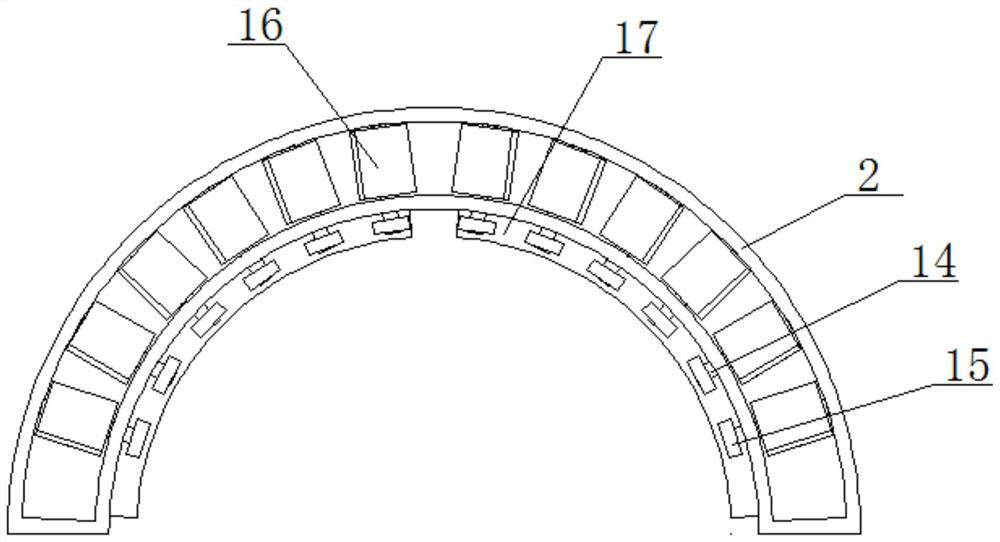
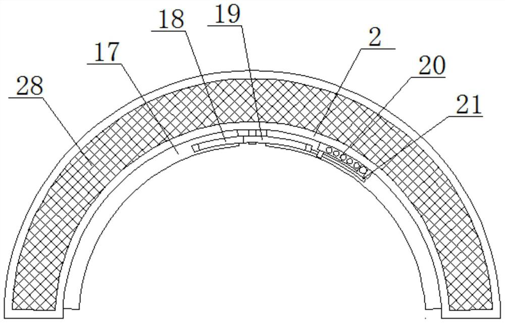
[0030] Such as Figure 1-6 The shown tunnel piston pressure relief device includes a support ring 1, a plurality of support rods 3 are slidingly connected at equal intervals in the support ring 1, and one end of the plurality of support rods 3 extends to the outside of the support ring 1 and is fixedly installed There is the same buffer ring 2, a plurality of support shafts 14 are symmetrically rotated and connected in the buffer ring 2, and the bottom ends of the plurality of support shafts 14 all extend to the bottom of the buffer ring 2, and the bottom of the buffer ring 2 is symmetrically slidably connected with two Transmission rack 17, two transmission racks 17 are connected in transmission, the bottom end of the support shaft 14 is fixedly equipped with a rotating gear 15, and the transmission rack 17 is respectively meshed with a plurality of rotating gears 15 on the same sid...


PUM


Abstract

The invention belongs to the field of tunnels, and particularly relates to a tunnel piston pressure relief device. The device is characterized in that a plurality of supporting rods are slidably connected into a supporting ring at equal intervals, one ends of the supporting rods extend to the outer side of the supporting ring and are fixedly provided with a same buffer ring, and a plurality of supporting shafts are symmetrically and rotationally connected into the buffer ring; and the bottom ends of the plurality of supporting shafts extend to the position below the buffer ring, two transmission racks are symmetrically connected to the bottom of the buffer ring in a sliding mode and are in transmission connection, rotating gears are fixedly installed at the bottom ends of the supporting shafts, the transmission racks are engaged with the multiple rotating gears located on the same side correspondingly, and the supporting shafts are fixedly sleeved with flow guide plates located in thebuffer ring. According to the device, when a train enters a tunnel, two-stage buffer damping can be achieved on generated strong air flow, so that the air speed is effectively reduced, good protectioncan be provided when the train enters the tunnel, and good safety is achieved.

Description

technical field [0001] The invention belongs to the technical field of tunnels and relates to a tunnel piston pressure relief device. Background technique [0002] After the train enters the tunnel, the body shakes more violently because of the piston effect. [0003] Air vibration in railway tunnels means that when high-speed trains such as trains, high-speed trains or high-speed trains enter the railway tunnel, the train instantly squeezes the air at the tunnel entrance to form a high-pressure wave, which is reflected by the tunnel and then squeezes the train, so the high-speed situation The train will produce a certain degree of vibration when entering the tunnel mouth, this effect is called the piston effect; [0004] At present, my country is researching a high-speed maglev train with a speed of 600Km / h. The speed of this high-speed maglev train is 2-3 times that of the existing high-speed rail. When it enters the tunnel, the air vibration will be more severe, which ma...

Claims


Application Information

Patent Timeline
Patent Type & Authority Applications(China)
IPC IPC(8): E21F17/00B61B13/10
CPCB61B13/10E21F17/00
Inventor 瞿启芳
Owner 瞿启芳
Learn More