Primary positioning method for penetrating type scanning light source

A penetrating, light source technology, applied in the direction of character and pattern recognition, instruments, computer parts, etc., can solve the problems of increased maintenance opportunities, space waste, cost increase, etc., and achieve the reduction of failure probability, cost reduction, qualified rate-enhancing effect

Inactive Publication Date: 2003-09-24
BENQ CORP
View PDF1 Cites 0 Cited by
  • Summary
  • Abstract
  • Description
  • Claims
  • Application Information

AI Technical Summary

Problems solved by technology

[0006] This method of using the position detector to position the lamp tube requires additional components and circuits in design, resulting in waste of space, increased cost, difficulty in assembly, and increased maintenance opportunities

Method used


Image

  • Primary positioning method for penetrating type scanning light source
  • Primary positioning method for penetrating type scanning light source
  • Primary positioning method for penetrating type scanning light source

Examples


Embodiment Construction

[0026] Detailed description of the preferred embodiment

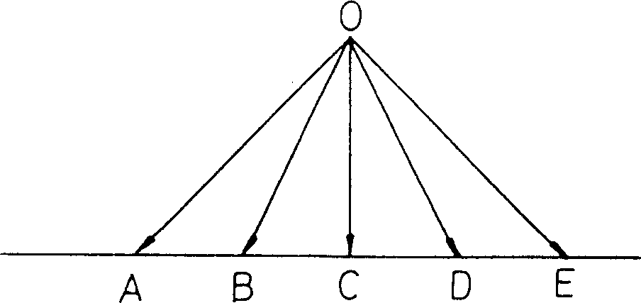
[0027] The influence of optical path on brightness is explained below. Referring to Figure 1, according to the optical principle, since the OA distance > OB distance > OC distance, if the same light source is used to illuminate points A, B, and C, the brightness of point A OD distance > OC distance. Therefore: the brightness of point E < the brightness of point D < the brightness of point C. In general: the measured brightness of point C is the largest.

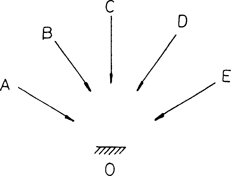
[0028] The influence of the incident angle on the brightness is explained below. refer to figure 2 , because the incident angle ∠AOC>∠BOC>∠COC, if the same light source is used to irradiate positions A, B, and C, the brightness of A at point O ∠DOC>∠COC, so the brightness of E at point O < the brightness of D at point O < the brightness of C at point O, so the brightness of the light source at point C is the largest.

[0029] Therefore, when the body of the image...


PUM


Abstract

A method for initial positioning of a transmissive scanning light source in an image reading device, comprising the steps of: (1) positioning the scanning module at a corresponding position x for reading a predetermined pattern of the reference area, and the corresponding position x is relative to the The distance around the bearing area is Δx; (2) move the scanning light source from the bearing area to the reference area, and start the scanning module to read the image; (3) repeat step (2) until it is determined that the The image read by the scanning module satisfies a predetermined rule, and it is known that the distance moved by the scanning light source during the determination process is Δd; (4) Make the scanning light source follow the original moving direction of step (2) and continue Move the distance of ΔD-Δd-Δx.

Description

technical field [0001] The invention relates to a method for positioning and adjusting the initial position of a light source of a transmissive image reading device. Background technique [0002] With the advancement of technology, the functions of image reading devices are increasing day by day. Generally speaking, as long as the top cover of the reflective image reading device is removed, and the reflective image reading device is added with a transparency light source module, it can scan positive films such as slides and negative films. Materials such as translucent properties. That is, the image of the object to be scanned is illuminated by the light source in the transmissive light source module, and the data is received by the image reading device (CCD) in the image reading device. [0003] When performing penetrating scanning, the light source (lamp tube on one side of the scanned object) in the penetrating light source module moves synchronously with the scanning m...

Claims


Application Information

Patent Timeline
Patent Type & Authority Patents(China)
IPC IPC(8): G06K9/32
Inventor 吴秉旭林品旭唐建兴
Owner BENQ CORP
Why Eureka
Try Eureka