
Laser annealing device

A laser annealing and laser technology, applied to lasers, laser components, phonon exciters, etc., can solve problems such as laser size or shape changes, irradiation position shaking, annealing process variables, etc.

Pending Publication Date: 2021-02-26
COWIN DST CO LTD
View PDF0 Cites 0 Cited by
  • Summary
  • Abstract
  • Description
  • Claims
  • Application Information

AI Technical Summary

Problems solved by technology

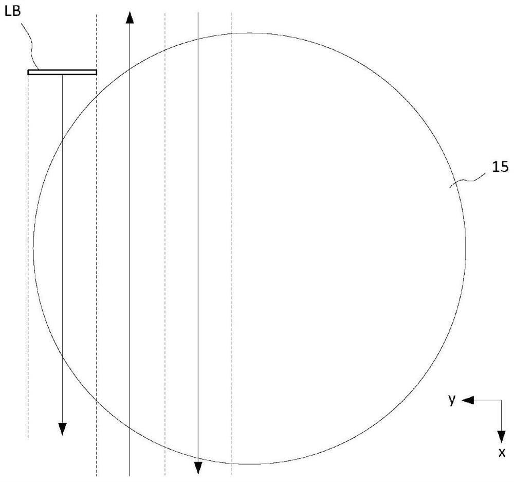
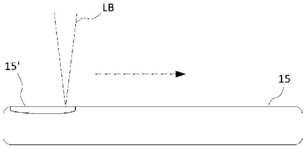
[0019] However, the above-mentioned conventional laser annealing device has the following problems: due to unstable factors such as the laser light source or the optical system components themselves or the joint structure on the traveling path of the laser light, the optical axis moves or the angle is twisted, so that the laser light reaches The irradiation position on the substrate fluctuates, and the size or shape of the laser changes, resulting in variables in the annealing process

Method used


Image

  • Laser annealing device
  • Laser annealing device
  • Laser annealing device

Examples


Embodiment Construction

[0042] The present invention will be described in more detail below through detailed embodiments of the present invention with reference to the accompanying drawings.

[0043] Figure 4 It is a conceptual diagram showing the configuration of a laser annealing apparatus according to an embodiment of the present invention.

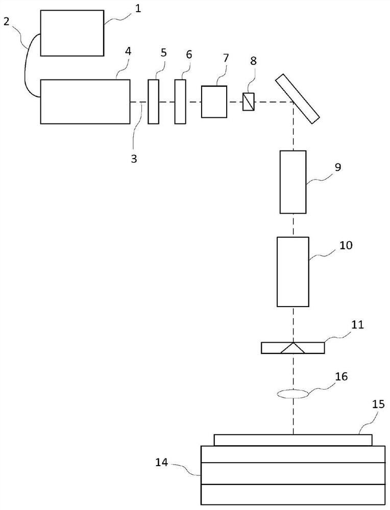
[0044] refer to Figure 4 , the present embodiment is formed by the following structure in the same way as in the past: a laser light source 110, which emits laser light; a laser correction part, which is used to check the laser state and path of the laser light emitted from the laser light source 110 reaching the substrate 115 and correct it according to the inspection result. The state and path of the laser light; the laser shaping unit 140, which receives the laser light radiated from the laser light source 110 and passes through the first correction unit of the laser correction unit, and then shapes the line beam with a predetermined size and form to th...


PUM


Abstract

Disclosed is a laser annealing device comprising: a laser light source for emitting a laser light; a laser light shaping unit, which receives the laser light emitted from the laser light source so asto shape same into a line beam of a certain size and shape; an imaging optical system, which focuses the shaped laser light while passing same therethrough so as to emit the focused laser light at a substrate to be annealed; and a substrate stage capable of loading the substrate thereon and moving same onto a plane that is parallel to a substrate surface, and further comprising a laser light correction unit for inspecting the state and path of a laser light until the laser light emitted from the laser light source reaches the substrate, and correcting the state and path of the laser light according to the inspection result. According to the present invention, changes in the path or state of a laser light, caused by the instability of a laser light source and an optical element on a path, are corrected such that light emittance for laser annealing can be performed at an accurate location of a substrate on a stage.

Description

technical field [0001] The present invention relates to a laser annealing device for performing laser annealing on a semiconductor substrate, and more specifically, to a laser annealing device capable of solving the problems of laser instability or irradiation displacement during the laser annealing process. Background technique [0002] Annealing refers to one of the heat treatment methods for the object to be processed. In the field of semiconductors or display devices, annealing generally refers to the process of uniformly distributing or activating injected impurities through rapid heating and slow cooling heat treatment, or, Processing methods used for semiconductor crystal defect elimination, etc. [0003] Stove equipment or electric lamp devices can also be used in this type of annealing device, but recently, more and more developments are used to rapidly increase the temperature in a short period of time, and concentrate the energy on a specific area of ​​​​the objec...

Claims


Application Information

Patent Timeline
Patent Type & Authority Applications(China)
IPC IPC(8): H01L21/67C21D10/00H01S3/10
CPCH01L21/67H01S3/10C21D10/00H01L21/67098H01L21/67248C21D10/005
Inventor 金仙株河载均苏裕真
Owner COWIN DST CO LTD
Learn More