Method for realizing LED lamp dimming by using switch, LED lamp dimming system and LED lamp

A technology for LED lights and dimming, which is applied to electrical components and other directions, can solve the problem of not being easy to use, and achieve the effects of easy use, simple dimming method, and convenient use.

Pending Publication Date: 2021-01-15
SHENZHEN TOPBAND CO LTD
View PDF4 Cites 0 Cited by
  • Summary
  • Abstract
  • Description
  • Claims
  • Application Information

AI Technical Summary

Problems solved by technology

However, because the lamp itself cannot be connected with an external dimming line on the wiring, the dimming methods of LED dimming lamps on the market are mainly: 0-10V or 1-10V dimming, thyristor dimming, PWM dimming, and secondly Need to match the corresponding dimmer, or need to match the gateway, sensor, remote control, etc., or external power supply to achieve dimming, the circuit needs to be modified when replacing, and it is not easy to use

Method used


Image

  • Method for realizing LED lamp dimming by using switch, LED lamp dimming system and LED lamp
  • Method for realizing LED lamp dimming by using switch, LED lamp dimming system and LED lamp
  • Method for realizing LED lamp dimming by using switch, LED lamp dimming system and LED lamp

Examples


Embodiment Construction

[0039] In order to have a clearer understanding of the technical features, purposes and effects of the present invention, the specific implementation manners of the present invention will now be described in detail with reference to the accompanying drawings.

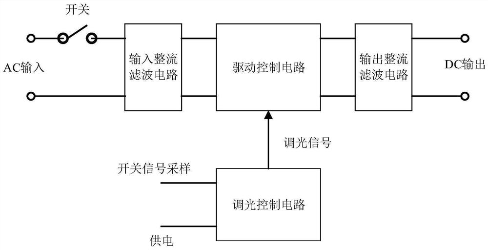
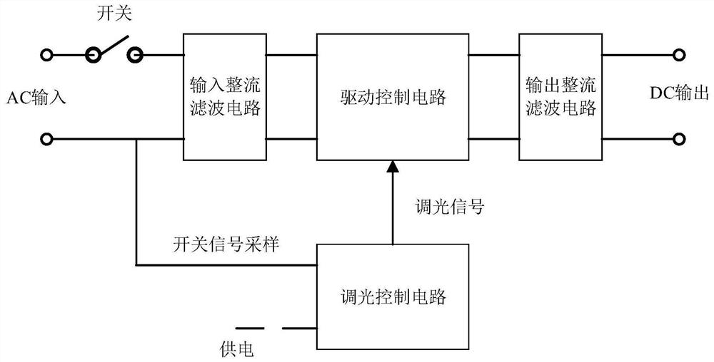
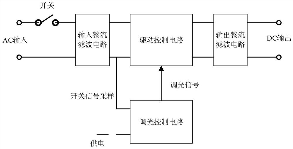
[0040] refer to figure 1 , is a structural schematic diagram of the LED lamp dimming system provided by the present invention. The LED light dimming system includes: a switch, an input rectification filter circuit, a drive control circuit, an output rectification filter circuit, and a dimming control circuit;

[0041] Specifically, the AC input end is connected to the input end of the input rectification filter circuit through the switch, the output end of the input rectification filter circuit is connected to the input end of the output rectification filter circuit through the drive control circuit; the output end of the output rectification filter circuit is connected to the DC output end connection; the dimming end ...


PUM


Abstract

The invention relates to a method for realizing LED lamp dimming by using a switch, an LED lamp dimming system and an LED lamp. The method comprises the following steps of reading a stored dimming signal data value; judging whether the dimming signal data value is a reset value or not; if yes, outputting a first dimming signal which changes circularly according to a preset change rule to a drivingcontrol circuit so that the driving control circuit outputs a corresponding driving current to enable the brightness of the LED lamp to change circularly according to a certain rule; judging whethera switching signal is received or not; if so, storing the dimming signal data value corresponding to the first dimming signal output at the moment and keeping the dimming signal data value unchanged;a second dimming signal corresponding to the stored dimming signal data value being outputted to the driving control circuit so that the driving control circuit outputs a corresponding driving currentto enable the LED lamp to emit light with corresponding brightness; judging whether a reset signal is received or not; and if so, setting the stored dimming signal data value as a reset value. The LED lamp can be directly replaced for use without changing the wiring mode of the LED lamp, cost is low, and dimming is easy and convenient.

Description

technical field [0001] The invention relates to the field of LED lighting control, and more specifically relates to a method for realizing dimming of an LED lamp by using a switch, a dimming system for the LED lamp and an LED lamp. Background technique [0002] DLC (Design Lights Consort) V5.1 version requires LED lamps to have dimming function. However, because the lamp itself cannot be connected with an external dimming line on the wiring, the dimming methods of LED dimming lamps on the market are mainly: 0-10V or 1-10V dimming, thyristor dimming, PWM dimming, and secondly It needs to be equipped with a corresponding dimmer, or needs to be equipped with a gateway, sensor, remote control, etc., or an external power supply to achieve dimming. When replacing, the circuit needs to be modified, and it is not easy to use. Contents of the invention [0003] The technical problem to be solved by the present invention is to provide a method for dimming an LED lamp by using a swi...

Claims


Application Information

Patent Timeline
Patent Type & Authority Applications(China)
IPC IPC(8): H05B45/325H05B45/36H05B45/10H05B47/175H05B47/165
CPCH05B45/325H05B45/36H05B45/10H05B47/175H05B47/165
Inventor 杨清华彭文福
Owner SHENZHEN TOPBAND CO LTD
Why Eureka
Try Eureka