Intelligent local and remote dimming method for LED lamp

A kind of LED light, intelligent technology, applied in the field of intelligent local and remote dimming of LED lights, can solve the problems that local and remote dimming cannot be realized at the same time, and achieve the effect of easy operation, simple dimming method, and realization of adjustment control

Inactive Publication Date: 2017-07-07
ULTIMATE IOT (SHANGHAI) TECH LTD
View PDF10 Cites 4 Cited by
  • Summary
  • Abstract
  • Description
  • Claims
  • Application Information

AI Technical Summary

Problems solved by technology

[0003] The purpose of the present invention is to provide an intelligent local and remote dimming method for LED lamps, which solves the problem that traditional LED lamp dimming methods generally only use local dimming, so that local and remote dimming cannot be realized at the same time

Method used


Image

  • Intelligent local and remote dimming method for LED lamp
  • Intelligent local and remote dimming method for LED lamp
  • Intelligent local and remote dimming method for LED lamp

Examples


Embodiment 1

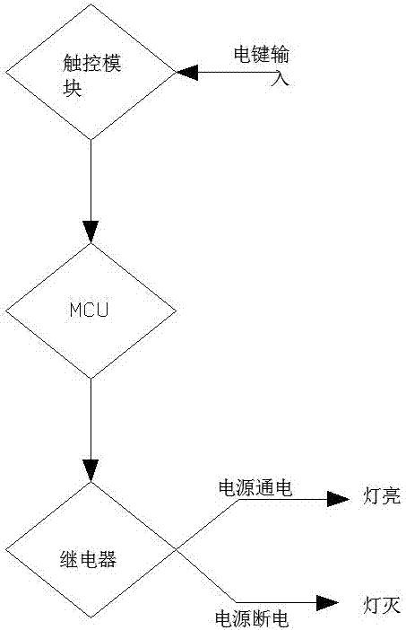
[0034] Such as figure 1 As shown, the specific process of local control of LED lights to turn on or off the lights includes the following:

[0035] Step 1. Single press the dimming button once, and the touch module recognizes the button action to obtain an instruction to turn on or turn off the light, and send the obtained instruction to the microcontroller;

[0036] Step 2, the single-chip microcomputer determines the key command, and processes the key command, and feeds back the processed command to the relay module;

[0037] Step 3. The relay module controls the input of the power supply according to different commands. When the relay receives the command to turn on the light, the single-chip microcomputer controls the relay to pull in to control the power supply of the LED, and the LED light is on. When the relay receives the command to turn off the light, the single-chip microcomputer controls the relay. Separate to control the LED power supply to power off, and the LED ...

Embodiment 2

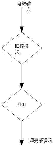
[0040] Such as figure 2 As shown, the specific process of local adjustment and dimming of LED lights includes the following:

[0041] Step 1. Press and hold the dimming button, and identify the button action for the touch module to obtain a brightening or dimming command, and send the obtained command to the microcontroller;

[0042] Step 2. When the button signal is a dimming command, the PWM duty cycle output by the PWM pin on the microcontroller becomes larger, and the output voltage becomes larger at this time, and the LED light becomes brighter. When the button signal is a dimming command, the microcontroller on the The PWM duty cycle output by the PWM pin becomes smaller, and the output voltage becomes smaller at this time, and the LED light becomes darker.

Embodiment 3

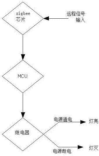
[0044] Such as image 3 As shown, the specific process of remotely controlling the LED lights to turn on or off the lights includes the following:

[0045] Step 1. The remote terminal transmits a light-on or light-off signal to the zigbee chip, and then the zigbee chip sends the remote signal to the microcontroller;

[0046] Step 2, the single-chip microcomputer judges the remote signal, processes the remote signal, and feeds back the processed signal to the relay module;

[0047] Step 3. The relay module controls the input of the power supply according to the different signals. When the relay receives the signal to turn on the light, the single-chip microcomputer controls the relay to pull in to control the power supply of the LED, and the LED light is on. When the relay receives the signal to turn off the light, the single-chip microcomputer controls the relay. Separate to control the LED power supply to power off, and the LED light is off.


PUM


Abstract

The invention discloses an intelligent local and remote dimming method for an LED lamp. An LED intelligent dimming switch is arranged and consists of an AC-DC converter power module, a single-chip microcomputer module, a zigbee communication circuit module, a touch control module and a relay module; the single-chip microcomputer module is connected with the zigbee communication circuit module, the touch control module and the relay module; and the AC-DC converter power module provides power for the single-chip microcomputer module. The dimming method comprises steps of key scanning, zigbee remote controlling and single-chip microcomputer signal processing. The dimming method has the following beneficial effects: the dual functions of local controlling and remote controlling can be realized and thus adjustment controlling of brightness of an LED lamp can be realized. Moreover, the dimming method is simple and is easy to operate.

Description

technical field [0001] The invention relates to a dimming method for an LED lamp, in particular to an intelligent local and remote dimming method for an LED lamp. Background technique [0002] With the advancement of technology, the use of household lighting fixtures and LED lights has become more and more common, but the use of LEDs has also brought about the difficulty of dimming. At present, household LED dimming mostly uses mechanical knobs to generate a DC voltage of 1-10V. signal to control the adjustable driving power of LED lights; but this cannot solve the problem that the smart home system can not only adjust the light manually locally, but also remotely adjust the light through the client or through other trigger conditions. Contents of the invention [0003] The purpose of the present invention is to provide an intelligent local and remote dimming method for LED lamps, which solves the problem that the traditional LED lamp dimming methods generally only use...

Claims


Application Information

Patent Timeline
Patent Type & Authority Applications(China)
IPC IPC(8): H05B33/08H05B37/02H05B44/00
CPCH05B45/37H05B47/19Y02B20/40
Inventor 叶龙马涛李银伟张松涛
Owner ULTIMATE IOT (SHANGHAI) TECH LTD
Why Eureka
Try Eureka