Printing control strip with split mark

A technology of marking and measuring strips, applied in printing, printing machines, general parts of printing machinery, etc., can solve problems such as quality loss

Active Publication Date: 2016-05-25
HEIDELBERGER DRUCKMASCHINEN AG
View PDF9 Cites 4 Cited by
  • Summary
  • Abstract
  • Description
  • Claims
  • Application Information

AI Technical Summary

Problems solved by technology

Here, a quality loss that cannot be directly determined due to possible deviations of the intermediate values

Method used


Image

  • Printing control strip with split mark
  • Printing control strip with split mark
  • Printing control strip with split mark

Examples


Embodiment Construction

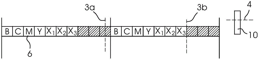
[0015] figure 1 Two adjacent ink zones 8 are shown, which each have ten ink measurement areas 6 , of which the last three ink measurement areas 6 form the peripheral marking 9 . In addition, two sensors 3 a and 3 b are provided, which are arranged offset by 7.5 times the ink measuring range.

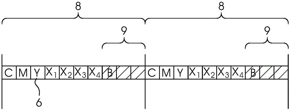
[0016] figure 2 Also shown are two adjacent ink zones 8 which each have ten ink measuring fields 6 , of which the last three ink measuring fields 6 form peripheral markings 9 , And the above-mentioned two sensors 3a and 3b are provided, which are arranged offset by 7.5 times the ink measurement area. In this case, the above-mentioned last three ink measurement regions 6 which form the peripheral marking 9 are set to be black in ink.

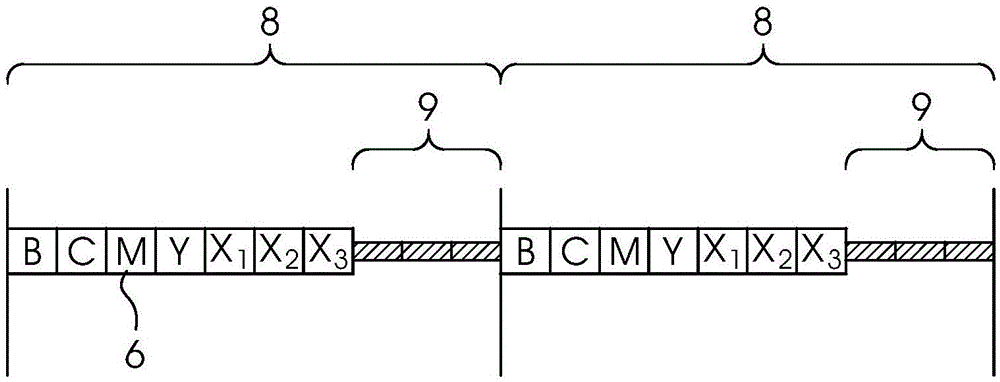
[0017] image 3 Also shown are two adjacent ink zones 8 which each have ten ink measuring fields 6 , of which the last three ink measuring fields 6 form peripheral markings 9 , And the above-mentioned two sensors 3a and 3b are provided, which are arr...


PUM


Abstract

The present invention relates to an apparatus for adjusting and conotrolling the position of a printing material in the circumferential direction in a printing materials processing machine. At least three sensors are comprised in the apparatus, one of which detects the lateral position and other two of which detect a circumferential register. The invention is characterized in that the two sensors of the circumferential register are laterally offset in many times and a fraction of a printing ink measurement field, the two sensors of the circumferential register detect an edge of a printing ink measuring strip of the printing ink measurement field, or detect the edge of the printing ink measuring strip and a mark on the printing material; the lateral sensor can analyze the following sensor; and the analyze range of the sensor is arranged in the printing ink measurement field or in the mark.

Description

technical field [0001] The invention relates to a device for adjusting and controlling the position of a printing material in the peripheral direction in a machine for processing printing materials, which has the features of claim 1 . Background technique [0002] For quality monitoring of the printed image, a printed monitoring strip is applied to the substrate at the sides of the original printed image. The print monitoring strip has a plurality of ink zones, which in turn consist of a continuously repeating sequence of ink measurement zones. Typically, one ink zone is 32.5 mm wide and has ten ink measurement areas of the same size. If the printing process is followed by other production process steps, a portion of the additional markings are required on the substrate. This is for example the case for die-cut printed products. Here, the printed product must be introduced into the die-cutter in the correct position, as otherwise errors and rejection of the final product ...

Claims


Application Information

Patent Timeline
Patent Type & Authority Applications(China)
IPC IPC(8): B41F33/14B65H7/10
CPCB41F33/0081
Inventor D·雅恩A·米勒
Owner HEIDELBERGER DRUCKMASCHINEN AG
Why Eureka
Try Eureka