Device capable of freely adjusting flow for valve positioner

A technology for valve positioner and flow adjustment, which is applied in the direction of valve energy absorbing devices, valve devices, valve details, etc. It can solve the problems of free adjustment control, ineffective flow, and no throttling structure, so as to achieve convenient and fast use , not easy to get stuck, good sealing effect

Pending Publication Date: 2021-01-19
SHENZHEN MORC CONTROLS
View PDF0 Cites 0 Cited by
  • Summary
  • Abstract
  • Description
  • Claims
  • Application Information

AI Technical Summary

Problems solved by technology

[0004] The purpose of the present invention is to provide a device for valve positioner that can freely adjust the flow rate to solve the above-mentioned background technology: in the prior art, some such devices do not have a throttling structure, and some have The throttling structure, the one without throttling structure generally adopts the way of adding throttling plate to throttling, while the usual valve positioner pressure gauge module with throttling structure usually adopts the structure of conical throttling rod to throttling, in In actual application, the method of adding a throttling plate is cumbersome to operate, and it can only be a fixed flow rate. However, the conical throttling structure cannot effectively adjust and control the flow rate freely, and because most of them are fixed by threaded connections The thread is very easy to get stuck when used for a long time in a more complex outdoor environment, resulting in the problem of being unusable

Method used


Image

  • Device capable of freely adjusting flow for valve positioner
  • Device capable of freely adjusting flow for valve positioner
  • Device capable of freely adjusting flow for valve positioner

Examples


Embodiment Construction

[0037] The following will clearly and completely describe the technical solutions in the embodiments of the present invention with reference to the accompanying drawings in the embodiments of the present invention. Obviously, the described embodiments are only some, not all, embodiments of the present invention. Based on the embodiments of the present invention, all other embodiments obtained by persons of ordinary skill in the art without making creative efforts belong to the protection scope of the present invention.

[0038]In the description of the present invention, it should be noted that the terms "upper", "lower", "inner", "outer", "front end", "rear end", "both ends", "one end", "another end" The orientation or positional relationship indicated by etc. is based on the orientation or positional relationship shown in the drawings, and is only for the convenience of describing the present invention and simplifying the description, rather than indicating or implying that t...


PUM


Abstract

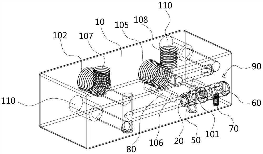
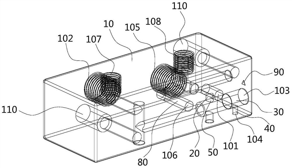
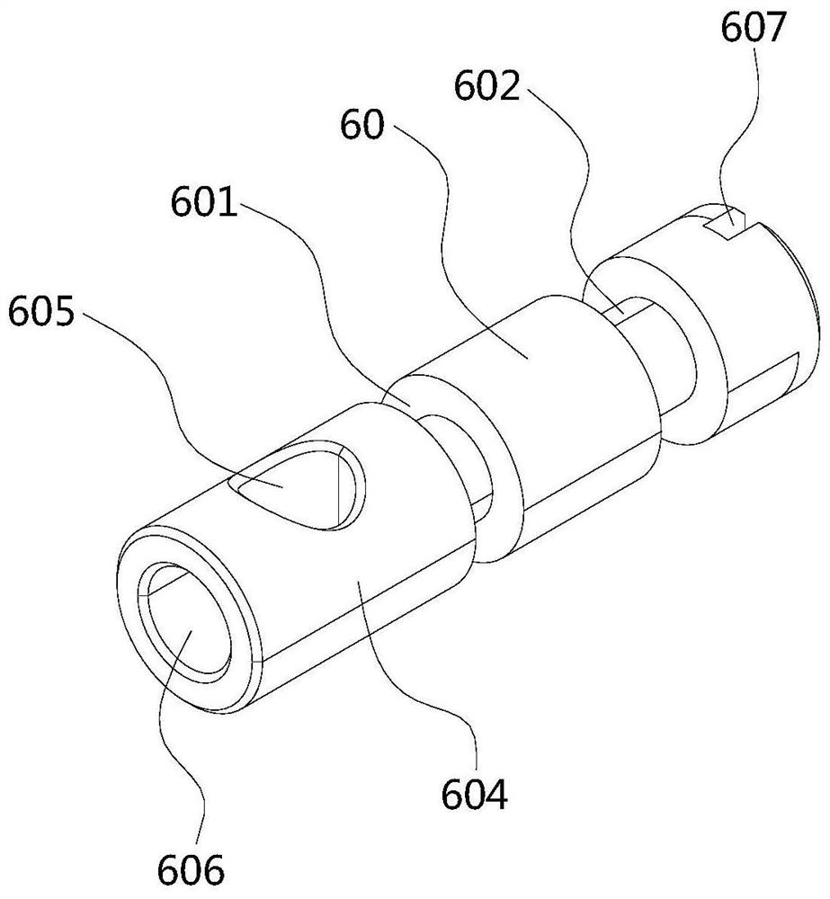
The invention discloses a device capable of freely adjusting flow for a valve positioner. The device comprises a device body, and a first air inlet, a first air outlet and a throttle lever opening areformed in the surface of the device body; and a first air channel communicating with the first air outlet and the first air inlet and a throttle lever channel communicating with the throttle lever opening in a matched manner are arranged in the device body, the throttle lever channel communicates with the first air channel in a crossed manner, and a communicating opening is formed in the crossedconnecting position of the throttle lever channel and the first air channel. According to the device, a throttling rod is arranged in the throttling rod channel of the device body, a blocking part anda first through hole part are arranged on the side face of the top of the throttling rod, a second through hole part is arranged at the top end of the throttling rod, and the effect of adjusting theflow of an output air source of the valve positioner is achieved through the through hole parts and the blocking part of the throttling rod.

Description

technical field [0001] The invention relates to the technical field of valve positioners, in particular to a device for valve positioners that can freely adjust flow. Background technique [0002] The valve positioner is the main accessory of the control valve. It uses the valve stem displacement signal as the input feedback measurement signal and the controller output signal as the setting signal for comparison. When there is a deviation between the two, it changes its output to the actuator The signal makes the actuator act, and establishes a one-to-one correspondence between the displacement of the valve stem and the output signal of the controller. Therefore, the valve positioner forms a feedback control system with the valve stem displacement as the measurement signal and the controller output as the setting signal. The manipulated variable of the control system is the output signal of the valve positioner to change the action of the actuator. [0003] Since the elect...

Claims


Application Information

Patent Timeline
Patent Type & Authority Applications(China)
IPC IPC(8): F16K37/00F16K47/10
CPCF16K37/0008F16K47/10
Inventor 莫荣张国灵
Owner SHENZHEN MORC CONTROLS
Why Eureka
Try Eureka