

Corrugated paper punching machine
A punching machine, corrugated paper technology, applied in metal processing and other directions, can solve problems such as can not prevent clogging
- Summary
- Abstract
- Description
- Claims
- Application Information
AI Technical Summary
Problems solved by technology
Method used
Image

Examples
specific Embodiment approach 1
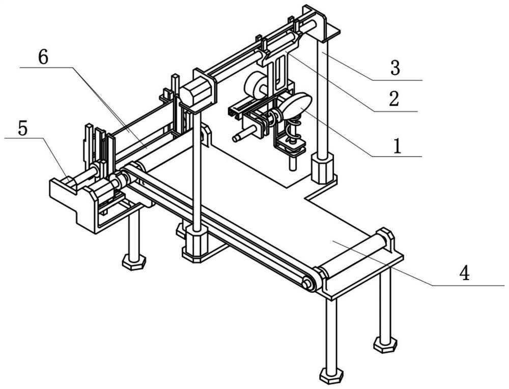
[0029] Combine below Figure 1-9 Describe this embodiment, a corrugated paper punching machine, including a punching assembly 1, a traverse assembly 2, a punching assembly 3, an intermittent feeding assembly 4, a frame driving assembly 5 and a cut-to-length assembly 6, the punching assembly 1 is rotatably connected to the traverse assembly 2, the punching assembly 1 and the traverse assembly 2 are meshed for transmission, the traverse assembly 2 is slidably connected to the stamping assembly 3, the traverse assembly 2 and the stamping assembly 3 are driven by threads, and the stamping assembly 3 is fixed Connected to the intermittent feed assembly 4, the frame drive assembly 5 is fixedly connected to the intermittent feed assembly 4, two cut-to-length assemblies 6 are provided, and the rear moving plate of the two cut-to-length assemblies 6 is slidably connected to the frame drive On the assembly 5, two cut-to-length assemblies 6 are all engaged with the frame driving assembly...
specific Embodiment approach 2
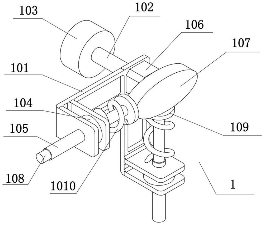
[0032] Combine below Figure 1-9 To illustrate this embodiment, the punching assembly 1 includes a punching frame 101, a rotating shaft 102, a rack gear 103, a mounting seat 104, a punch 105, an anti-blocking motor 106, an anti-blocking oval wheel 107, a cleaning rod 108, a contact Disc 109 and back-moving spring 1010, rotating shaft 102 are fixedly connected on the punching frame 101, and rack gear 103 is fixedly connected on the rotating shaft 102, and the front end and the lower end of punching frame 101 are all fixedly connected with mount 104, two Mounting base 104 is all connected with punch 105 by thread, anti-blocking motor 106 is fixedly connected on the punch frame 101, and anti-blocking oval wheel 107 is fixedly connected on the output shaft of anti-blocking motor 106, and both punches 105 are A cleaning rod 108 is slidably connected, and a contact disc 109 is fixedly connected to the two cleaning rods 108 , and a return spring 1010 is fixedly connected between the ...
specific Embodiment approach 3
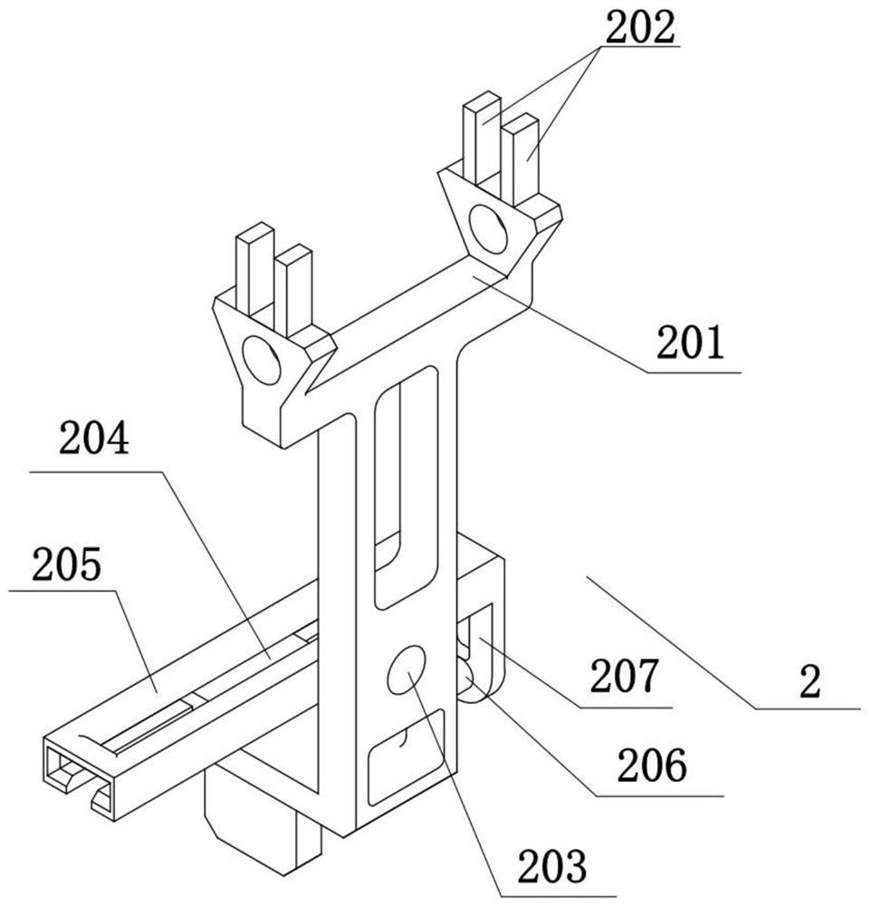
[0035] Combine below Figure 1-9 To illustrate this embodiment, the traversing assembly 2 includes a traversing frame 201, a sliding limit block 202, a rotation hole 203, a rack sliding frame 204, a rack 205, a reciprocating cylinder 206, and a rack connecting plate 207. The traversing frame Both front and rear sides of 201 are provided with two sliding limit blocks 202, and the lower end of the traversing frame 201 is provided with a rotating hole 203, the rotating shaft 102 is rotatably connected in the rotating hole 203, and the rack sliding frame 204 is fixedly connected to the traversing frame. On the left side of 201, the rack 205 is slidingly connected to the rack sliding frame 204, the rack gear 103 and the rack 205 are meshed for transmission, the reciprocating cylinder 206 is fixedly connected to the lower end of the traverse frame 201, and the rack connecting plate 207 is fixedly connected to On the cylinder rod of the reciprocating cylinder 206 and the rack 205.
...
PUM
 Abstract
Description
Claims
Application Information