Eureka AIR delivers breakthrough ideas for toughest innovation challenges, trusted by R&D personnel around the world.

Vibration assembly and electronic device with same

A technology of vibration components and electronic equipment, which is applied in the field of sensors, can solve problems such as inaccurate voice recognition of vibration components, failure to meet reliability requirements, and reduced sensitivity, and achieve the effects of reliable structure, improved sensitivity, and improved quality

Pending Publication Date: 2021-01-22
GEER INTELLIGENT TECH CO LTD
View PDF6 Cites 0 Cited by
  • Summary
  • Abstract
  • Description
  • Claims
  • Application Information

AI Technical Summary

Problems solved by technology

[0003] In the prior art, the vibrating assembly can include damping rubber, reeds and mass blocks, the reeds are attached to the damping rubber ring, and the mass block is attached to the upper surface of the reeds, through the vibration of the reeds and damping rubber, thereby Transmission of vibration signals; the vibration components set up in this way are prone to fatigue and instability due to the structural reasons of the reed and damping rubber, which makes the sensitivity reduced or invalid or unstable, especially under long-term use. Reliability can not meet the requirements
At the same time, based on the structure of the reed, the vibration component will also experience inaccurate speech recognition, insensitivity and even failure
[0004] In summary, how to provide a vibrating component with reliable structure, high sensitivity, more accurate speech recognition, simple structure, and low power is a technical problem that those skilled in the art need to think about

Method used


Image

  • Vibration assembly and electronic device with same
  • Vibration assembly and electronic device with same
  • Vibration assembly and electronic device with same

Examples


Embodiment Construction

[0036] The following will clearly and completely describe the technical solutions in the embodiments of the present invention with reference to the accompanying drawings in the embodiments of the present invention. Obviously, the described embodiments are only some, not all, embodiments of the present invention. Based on the embodiments of the present invention, all other embodiments obtained by persons of ordinary skill in the art without making creative efforts belong to the protection scope of the present invention.

[0037] In order to enable those skilled in the art to better understand the solution of the present invention, the present invention will be further described in detail below in conjunction with the accompanying drawings and specific embodiments.

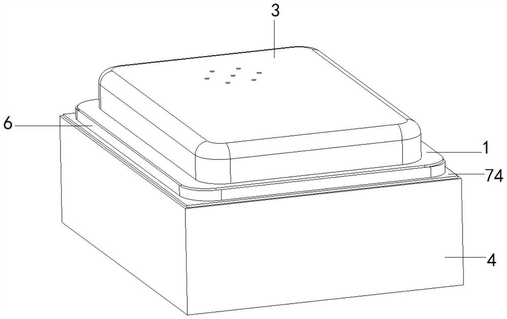
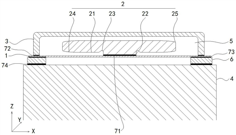
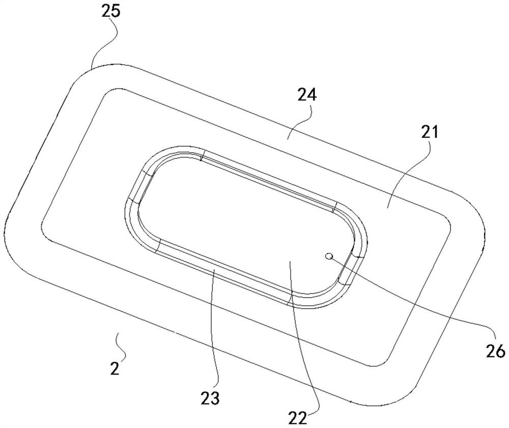
[0038] For the vibration assembly provided by the embodiment of the present invention, refer to the attached figure 1 to attach Figure 5 As shown, the diaphragm 1 and the mass block 2 are included, and the diaphra...


PUM


Abstract

The invention discloses a vibration assembly and an electronic device with the same. The vibration assembly comprises a vibrating diaphragm and a mass block, the end face, facing the vibrating diaphragm, of the mass block is provided with a protrusion, and the protrusion is connected with the vibrating diaphragm. The end face is provided with grooves located in the periphery of the protrusion, andthe grooves are adjacent to the protrusion. The peripheral edge of the end face is provided with an inclined plane, and the inclined plane extends in a direction deviating from the vibrating diaphragm along a direction deviating from the projection. Compared with like products in the prior art, the vibration assembly is higher in voice recognition sensitivity in the Z-axis direction, improves thesensitivity in the X-axis direction and the Y-axis direction, better expands the application of voice recognition, reduces the algorithm difficulty, enables the voice recognition to be more accurateand stable, and is expected to replace a three-axis structure with a simple low-power two-axis structure. A breakthrough application effect is brought to speech recognition, especially speech recognition of portable equipment, the structure is reliable, and the service life can be effectively prolonged.

Description

technical field [0001] The invention relates to the technical field of sensors, in particular to a vibrating component and electronic equipment with the vibrating component. Background technique [0002] For electronic devices such as vibration sensors, vibration components are usually required to convert vibration signals into electrical signals. [0003] In the prior art, the vibrating assembly can include damping rubber, reeds and mass blocks, the reeds are attached to the damping rubber ring, and the mass block is attached to the upper surface of the reeds, through the vibration of the reeds and damping rubber, thereby Transmission of vibration signals; the vibration components set up in this way are prone to fatigue and instability due to the structural reasons of the reed and damping rubber, which makes the sensitivity reduced or invalid or unstable, especially under long-term use. Reliability cannot meet the requirements. At the same time, based on the structure of ...

Claims


Application Information

Patent Timeline
Patent Type & Authority Applications(China)
IPC IPC(8): G01H17/00
CPCG01H17/00
Inventor 尹海昌
Owner GEER INTELLIGENT TECH CO LTD
Why Eureka
Eureka Blog
Learn More