Perforated cable tray bridge and wiring optimization structure thereof

A technology for cable trays and optimized structures, which is applied to electrical components, chemical instruments and methods, cleaning methods and appliances, etc. It can solve the problems of no limit and easy entanglement of cables, and achieve the effect of simple operation and convenient classification

Pending Publication Date: 2021-01-22
丰德信电力发展股份有限公司
View PDF1 Cites 2 Cited by
  • Summary
  • Abstract
  • Description
  • Claims
  • Application Information

AI Technical Summary

Problems solved by technology

[0004] The existing technology has the following disadvantages: the cables are pulled on the rollers, and when placing multiple cables, there is no limit between the cables, which are easy to be entangled and affect the use

Method used


Image

  • Perforated cable tray bridge and wiring optimization structure thereof
  • Perforated cable tray bridge and wiring optimization structure thereof
  • Perforated cable tray bridge and wiring optimization structure thereof

Examples


Embodiment Construction

[0024] The implementation mode of the present invention is illustrated by specific specific examples below, and those who are familiar with this technology can easily understand other advantages and effects of the present invention from the contents disclosed in this description. Obviously, the described embodiments are a part of the present invention. , but not all examples. Based on the embodiments of the present invention, all other embodiments obtained by persons of ordinary skill in the art without making creative efforts belong to the protection scope of the present invention.

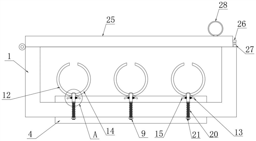
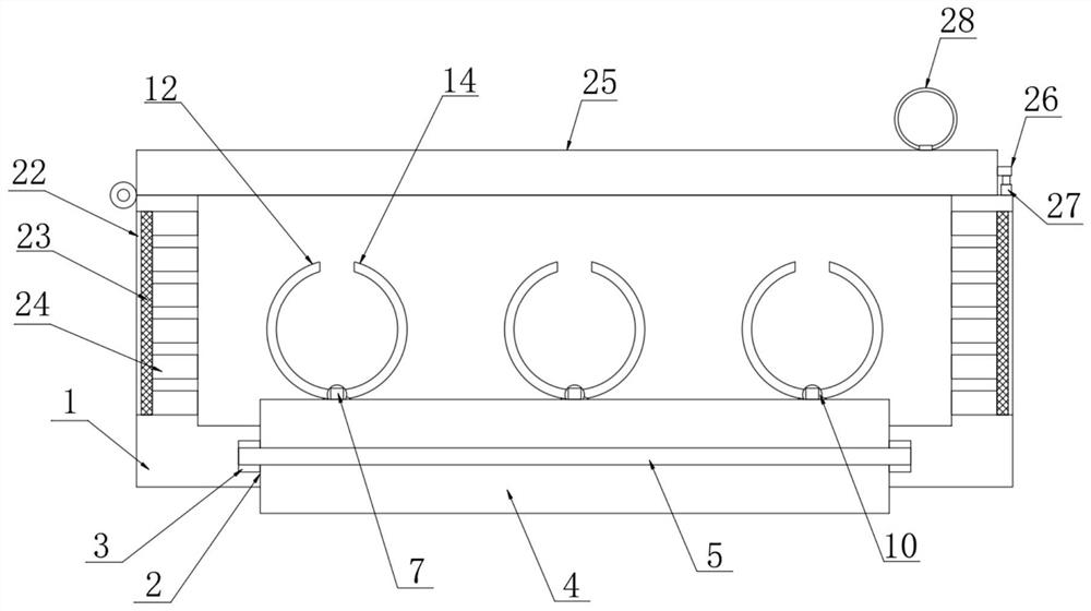
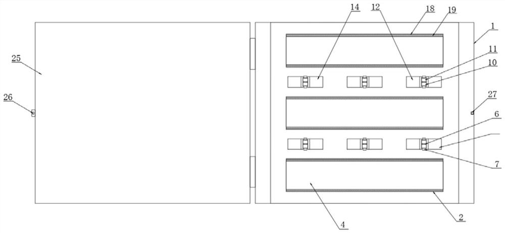
[0025] Refer to the attached Figure 1-5 , a perforated cable tray bridge and its wiring optimization structure in this embodiment, including a box body 1, openings are opened on both sides of the front and rear sides of the box body 1, and a plurality of grooves 2 are opened on the bottom surface of the box body 1 , the inner wall surfaces on both sides of the groove 2 are provided with slots 3...


PUM


Abstract

The invention discloses a perforated cable tray bridge and a wiring optimization structure thereof. The bridge comprise a box body, openings are formed in the front side and the rear side of the box body, a plurality of grooves are formed in the surface of the bottom of the box body, inserting grooves are formed in the surfaces of the inner walls of the two sides of each groove, carrier rollers are movably arranged in the grooves, and rotating shafts are movably arranged in the carrier rollers in a sleeving mode. The two ends of the rotating shafts are fixedly connected with the inner walls ofthe inserting grooves correspondingly, a plurality of round rods are arranged between the adjacent carrier rollers, supports are fixedly arranged at the front ends and the rear ends of the round rodscorrespondingly, and mounting plates are fixedly arranged at the bottoms of the supports. According to the invention, the first semicircular plates and the second semicircular plates are arranged inthe box body; the first semicircular plates and the second semicircular plates form clamps, so the first semicircular plates and the second semicircular plates are made to fix and limit the cables through the elastic force of the springs, and compared with the prior art, the operation is easy, and an operator can conveniently classify and arrange the multiple cables in the box body.

Description

technical field [0001] The invention relates to the field of cable tray bridges, in particular to a cable tray bridge with holes and an optimized wiring structure thereof. Background technique [0002] At present, the traditional cable tray includes two side plates and a bottom plate fixedly connected to the bottom edges of the two side plates, and an arc-shaped hook facing the inner side of the cable tray is provided at the top of the two side plates. During the wire pulling process, sliding friction occurs between the wire body and the bottom plate of the bridge frame, which easily leads to damage to the protective layer of the wire body and poor construction safety. At the same time, sliding friction will increase the output of manpower, which brings inconvenience to the work of relevant personnel. Cable bridge During the engineering process, thermal expansion and contraction will cause shrinkage problems, resulting in poor work safety. It needs to customize the correspon...

Claims


Application Information

Patent Timeline
Patent Type & Authority Applications(China)
IPC IPC(8): H02G3/14H02G3/08H02G3/04H02G3/03B08B1/00B08B1/02
CPCB08B1/002B08B1/02H02G3/03H02G3/0481H02G3/088H02G3/14
Inventor 朱佳晨曹睿李源
Owner 丰德信电力发展股份有限公司
Why Eureka
Try Eureka