Wafer inspection system for distinguishing pits and particles

a technology of inspection system and filter, applied in the direction of optical radiation measurement, semiconductor/solid-state device testing/measurement, instruments, etc., can solve the problem of wasting time and resources

Inactive Publication Date: 2001-09-18
ADE OPTICAL SYST
View PDF88 Cites 85 Cited by
  • Summary
  • Abstract
  • Description
  • Claims
  • Application Information

AI Technical Summary

Benefits of technology

When the scanned light beam contacts a defect, such as a pit or a particle, light is scattered from the surface and is collected by the collectors. The intensity of the scattered light, and the time of its detection during the scan, provide information about the size and location of the defect on the surface of the workpiece. Furthermore, the nature of the defect, i.e. whether it is a pit or a particle, can be ascertained by detecting differences in the angular distribution of the light scattered from the workpiece. For example, if the defect is a pit, the amount of light scattered and detected by the center channel collector is typically greater than that detected by the back channel collector. Alternatively, if the defect is a particle, the amount of the light detected by the center channel collector is typically less than that detected by the back channel collector and / or the forward channel collector. The dark channel collector system provides the surface inspection system of the present invention with high sensitivity to more readily identify, classify, and / or provide a topography of the condition of the surface of an article or a workpiece, including defects such as particles, pits and the like, in and on the surface of a workpiece.
The surface inspection system and method of the present invention advantageously distinguish pits in the surface of the wafer from particles on the surface of the wafer and therefore determine whether cleaning or some other course of action, e.g., altering the conditions of manufacture and storage, can be used to cure the defects. In addition, the surface inspection system and method provide high spatial resolution, a small field of view at the object plane which, in turn, provides improved edge detection performance, improved repeatability in the inspection process and reduces interference signals caused by scatter from air molecules.

Problems solved by technology

However, if the defects are pits or "COPS" (crystal originated pits) in the wafer surface, they are not removed by recleaning.
Because such surface inspection systems fail to distinguish between pit defects and particle defects, the wafer is typically sent back for recleaning regardless of whether the defects are pits or particles.
Because these defects may be pits, recleaning the wafer may result in nothing more than a waste of time and resources.

Method used


Image

  • Wafer inspection system for distinguishing pits and particles
  • Wafer inspection system for distinguishing pits and particles
  • Wafer inspection system for distinguishing pits and particles

Examples


Embodiment Construction

The present invention will be described more fully hereinafter with reference to the accompanying drawings in which specific embodiments of the invention are shown. This invention may, however, be embodied in many different forms and should not be construed as limited to the illustrated embodiments set forth herein; rather, these illustrated embodiments are provided so that this disclosure will be thorough and complete and will fully convey the scope of the invention to those skilled in the art. Like numbers refer to like elements throughout.

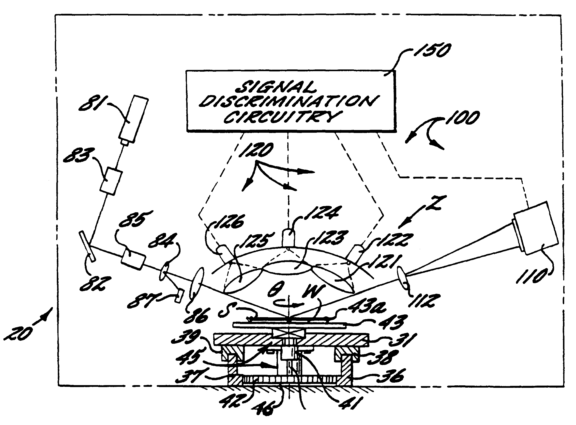
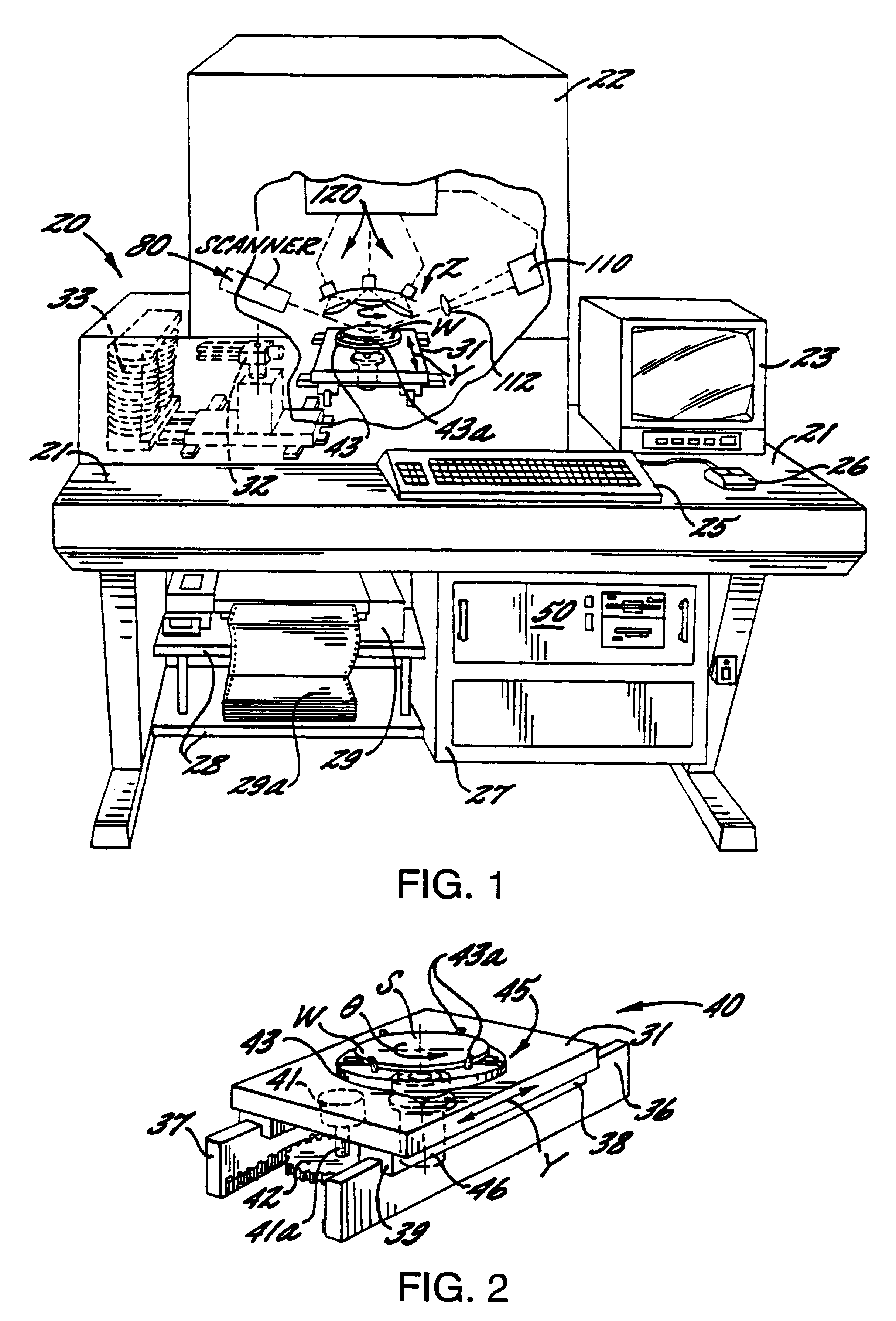
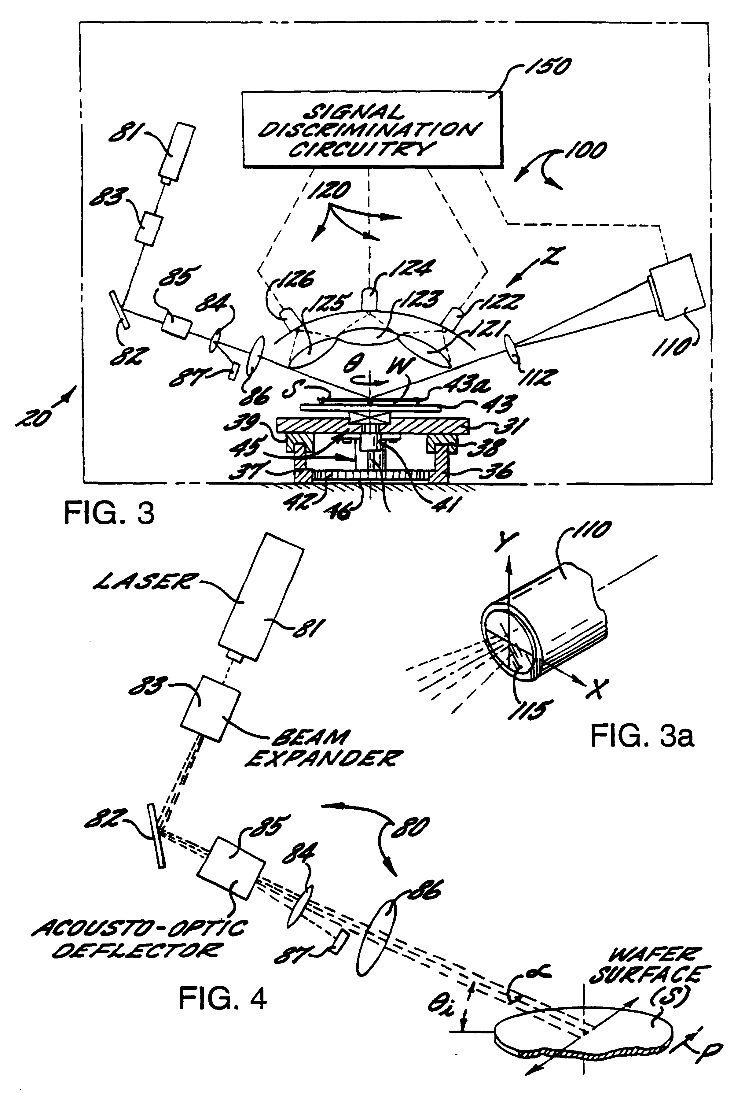
FIG. 1 is a perspective view of a surface inspection system 20 for detecting defects such as particles, pits and the like on a surface of a workpiece W or article, such as a silicon wafer. Portions of the system 20 are broken away for purposes of clarity and shown by phantom lines to illustrate various elements of the surface inspection system 20. The surface inspection system 20 is suitably used for inspecting the surface of unpatterned wafers ...


PUM

PropertyMeasurementUnit
sizeaaaaaaaaaa
diameteraaaaaaaaaa
angle of incidenceaaaaaaaaaa

Abstract

A surface inspection system and method is provided which detects defects such as particles or pits on the surface of a workpiece, such as a silicon wafer, and also distinguishes between pit defects and particle defects. The surface inspection system comprises an inspection station for receiving a workpiece and a scanner positioned and arranged to scan a surface of the workpiece at the inspection station. The scanner includes a light source arranged to project a beam of P-polarized light and a scanner positioned to scan the P-polarized light beam across the surface of the workpiece. The system further provides for detecting differences in the angular distribution of the light scattered from the workpiece and for distinguishing particle defects from pit defects based upon these differences.

Description

FIELD AND BACKGROUND OF THE INVENTIONThe present invention relates to surface inspection systems and methods and, more particularly, to the inspection of articles or workpieces, such as silicon wafers, to detect the presence of defects such as particles or pits on the surface and to distinguish therebetween.Surface inspection systems are commonly used for the inspection of articles or workpieces such as silicon wafers to detect the presence of defects on the wafer surface. When the inspection indicates a large number of defects, the wafer may be sent back for recleaning. If the defects are particles or other debris on the wafer surface, the recleaning is successful. However, if the defects are pits or "COPS" (crystal originated pits) in the wafer surface, they are not removed by recleaning. Because such surface inspection systems fail to distinguish between pit defects and particle defects, the wafer is typically sent back for recleaning regardless of whether the defects are pits or...

Claims


Application Information

Patent Timeline
Patent Type & Authority Patents(United States)
IPC IPC(8): G01N21/00G01N21/86
CPCG01N21/9501H01L22/12G01N2021/945
Inventor FOSSEY, MICHAEL E.STOVER, JOHN C.
Owner ADE OPTICAL SYST
Why Eureka
Try Eureka