Chair capable of correcting sitting postures and preventing humpback
A technology for correcting sitting posture and chairs, applied in chairs, massage aids, medical science, etc., can solve problems such as correcting sitting posture armrest adjustment, and achieve the effect of increasing friction and reducing fatigue.
- Summary
- Abstract
- Description
- Claims
- Application Information
AI Technical Summary
Problems solved by technology
Method used
Image
Examples
Embodiment 1
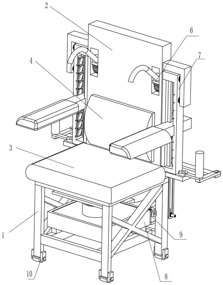
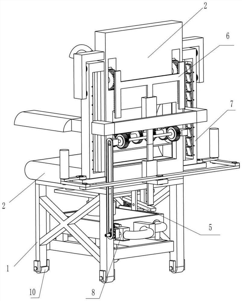
[0082] A chair that can correct sitting posture and prevent hunchback, such as figure 1 and figure 2 As shown, it includes a fixed frame 1, a support plate 2, a first sliding plate 3, an arc cushion 4, a drive mechanism 5 and a correction mechanism 6, the rear side of the top of the fixed frame 1 is provided with a support plate 2, and the top of the fixed frame 1 is provided with a support plate 2. There is a driving mechanism 5, the driving mechanism 5 is provided with a first sliding plate 3, the lower part of the front side of the support plate 2 is provided with an arc cushion 4, and a correction mechanism 6 is arranged between the back side of the support plate 2 and the driving mechanism 5.
[0083] People sit on the first sliding plate 3, leaning against the support plate 2, under the action of the arc-shaped cushion 4, people are prevented from hunchback, and at the same time, the first sliding plate 3 moves downward, and the first sliding plate 3 drives the driving ...
Embodiment 2
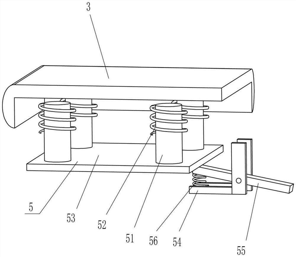
[0085] On the basis of Example 1, such as image 3 , Figure 4 , Figure 5 and Figure 10 As shown, the drive mechanism 5 includes a first guide rod 51, a first spring 52, a first fixed plate 53, a U-shaped fixed block 54, a swing bar 55 and a second spring 56, and the left and right sides of the top of the fixed frame 1 are all sliding Two first guide rods 51 are provided, and the tops of the first guide rods 51 are connected with the first slide plate 3, and the front and rear sides of the left and right sides of the bottom of the first slide plate 3 and the top of the fixed frame 1 are provided with first guide rods. The spring 52 and the first spring 52 are all set on the outside of the first guide rod 51 on the same side, the first fixed plate 53 is provided between the bottom of the first guide rod 51, and the U-shaped fixed block 54 is provided on the rear side of the upper part of the fixed frame 1. U-shaped fixed block 54 bottom rear side rotation type is provided ...
Embodiment 3
[0092] On the basis of Example 2, such as Figure 6 , Figure 7 , Figure 8 and Figure 9 As shown, massage mechanism 8 is also included, and massage mechanism 8 includes hydraulic box 81, telescoping rod 82, flexible pipe 83, hollow box 84, second rotating shaft 85, fan blade 86, reduction box 87, the 3rd rotating shaft 88, the 3rd rotating shaft A transmission assembly 89, a second column gear 810, a fourth rotating shaft 811, a third column gear 812, a first magnet 813, an arc plate 814, a second guide rod 815, a massage ball 816, a fourth spring 817, and a pull cord 818 With the second magnet 819, the bottom of the fixed frame 1 is provided with a hydraulic box 81, and the middle of the top of the hydraulic box 81 is provided with a telescopic rod 82, and the telescopic rod 82 cooperates with the first fixed plate 53. The right part of the pipe 83 is provided with a hollow box 84, the right side of the middle part of the rear side of the fixed frame 1 is provided with a...
PUM
 Abstract
Description
Claims
Application Information
 - R&D
- Intellectual Property
- Life Sciences
- Materials
- Tech Scout
- Unparalleled Data Quality
- Higher Quality Content
- 60% Fewer Hallucinations
Browse by: Latest US Patents, China's latest patents, Technical Efficacy Thesaurus, Application Domain, Technology Topic, Popular Technical Reports.
© 2025 PatSnap. All rights reserved.Legal|Privacy policy|Modern Slavery Act Transparency Statement|Sitemap|About US| Contact US: help@patsnap.com


