Combined inclined strut supporting pile

A supporting pile and combined technology, applied in sheet pile walls, excavation, construction, etc., can solve the problems of difficult excavation, long construction period, water leakage of the supporting body, etc., and achieves low cost, complete protection components, and increased size The effect of compressive stability

Inactive Publication Date: 2021-01-26
上海宝力通基础工程有限公司 +2
View PDF4 Cites 0 Cited by
  • Summary
  • Abstract
  • Description
  • Claims
  • Application Information

AI Technical Summary

Problems solved by technology

However, if the horizontal support is used, the construction cost will be higher and the earthwork excavation will be difficult; the use of the diagonal brace will lead to a longer construction period. On the other hand, if the environmental protection requirements of the foundation pit are high, the diagonal Pass through the underground structure, so the support system is prone to water leakage

Method used


Image

  • Combined inclined strut supporting pile
  • Combined inclined strut supporting pile
  • Combined inclined strut supporting pile

Examples


no. 1 example

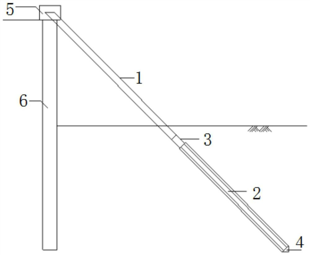
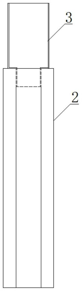
[0020] see figure 1 and figure 2 , the prefabricated pile 2 is a square pile, the mitered pile 1 is a steel pipe, the bracing connector 3 is a short steel pipe, the lower end of the short steel pipe is embedded in the top of the square pile, the upper end of the short steel pipe is connected to the inclined The bottom end of the steel pipe connecting pile 1 is connected.

[0021] The specific implementation method is as follows: the pile tip 4 is set at the pile end of the prefabricated pile 2; after the construction of the surrounding protection pile 6 is completed, the prefabricated pile 2 is driven obliquely, and the pile head is exposed to the ground; the prepared short steel pipe is embedded in the precast pile 2 and connected After completion, lift the miter pile 1 and connect it with the bracing connector 3; after the node connection is completed, continue to drive steel pipes to the design elevation; pour the ring beam 5 to form a whole.

[0022] Construction effect...

no. 2 example

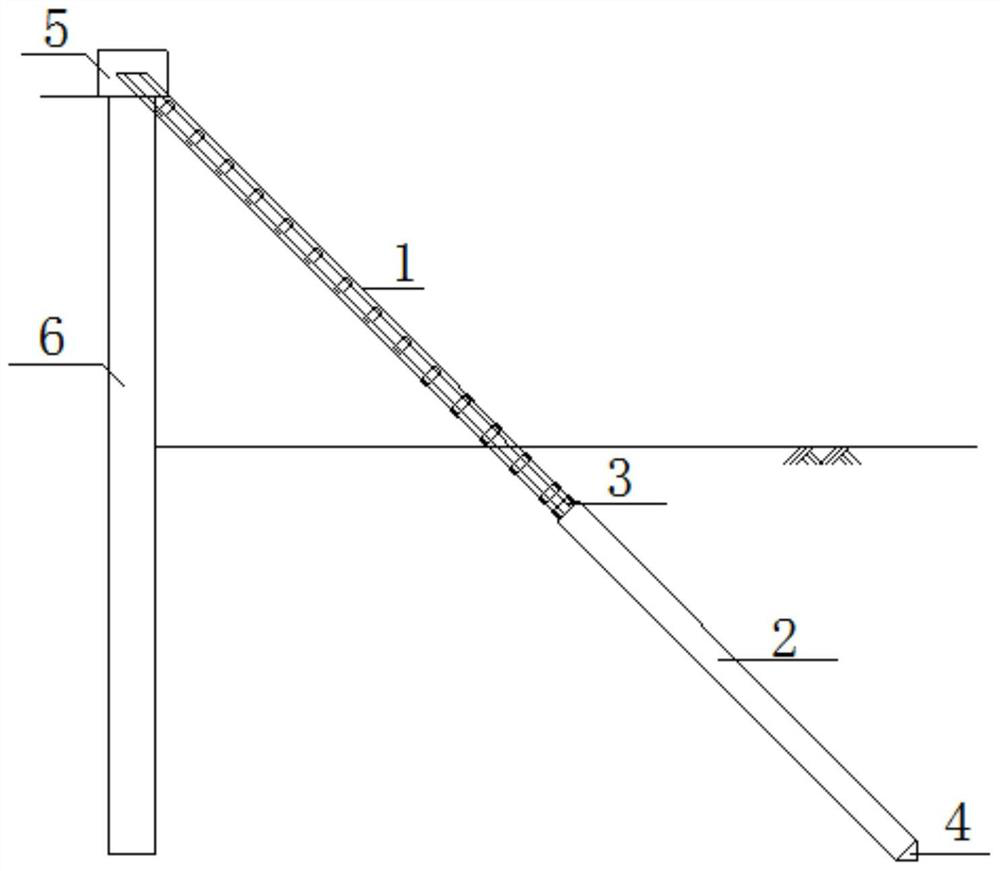
[0024] see image 3 and Figure 4 , the prefabricated pile 2 is a prefabricated square pile or a prefabricated pipe pile, the mitered pile 1 is a lattice column, and the diagonal brace connector 3 is an angle steel, and the lower end of the lattice column is connected to the prefabricated pile through the angle steel 2's upper connection.

[0025] The specific implementation method is as follows: the pile tip 4 is set at the pile end of the prefabricated pile 2, and the angle steel is set at the end plate of the pile head; The head is exposed to the ground; the lattice column is lifted and connected with the angle steel, and after the joint connection is completed, the lattice column is continued to be driven to the design elevation; the ring beam 5 is poured to form a whole.

[0026] Construction effect: ①The upper part adopts lattice columns to ensure the stability under pressure; the lower part adopts prefabricated piles (prefabricated square piles or prefabricated tubula...

no. 3 example

[0028] see Figure 5 and Figure 6 , the prefabricated pile 2 adopts a prefabricated square pile or a prefabricated pipe pile, the miter pile 1 adopts section steel, the diagonal bracing connector 3 adopts a rib plate, and a steel plate 7 and a prefabricated pile end plate 8 are arranged, and the rib plate and the steel plate 7 is fixedly connected to the lower end of the miter pile 1 and connected to the prefabricated pile end plate 8 at the top of the prefabricated pile 2 by bolts.

[0029] Further, a waterproof steel sheet 9 is also provided on the miter pile 1 .

[0030] The specific implementation method is as follows: set ribs and steel plates 7 at the lower end of the mitered pile 1 using section steel, and set the pile tip 4 at the pile end of the prefabricated pile 2; The head is exposed to the ground by about 1m; the mitered pile 1 is lifted, and the steel plate 7 and the prefabricated pile end plate 8 are connected by bolts; after the joint connection is completed...


PUM


Abstract

The invention discloses a combined inclined strut supporting pile. The combined inclined strut supporting pile comprises an inclined connecting pile, a precast pile, an inclined strut connecting piece, a ring beam and a fender pile, wherein the bottom end of the inclined connecting pile is removably connected with the upper part of the precast pile through the inclined strut connecting piece, thering beam is used for fixedly connecting the top of the inclined connecting pile with the top of the fender pile, and a pile toe is arranged on the bottom end of the precast pile so as to be driven underground. The combined supporting pile is convenient to construct, and the precast pile is adopted below the pit bottom, so that the bearing capacity of a pile body of an inclined strut is guaranteed, the stress mode of the inclined strut is optimized, the manufacturing cost is low, and the pile body can be lengthened to directly reach a supporting layer so as to adapt to various soil layers; thecompression stability of a free section is increased, and the bearing capacity of the soil layers can be utilized to the maximum extent; the pile toe and other measures are taken, so that vibration in a pile sinking process is reduced, and the integrity of components of a latticed column is protected; and a water stop steel sheet is arranged, so that the possibility of leakage after penetrating through a basement structure is reduced.

Description

technical field [0001] The invention relates to the field of building construction, in particular to foundation pit enclosure construction equipment, and in particular to a combined diagonal support pile. Background technique [0002] In the construction of conventional foundation pit support engineering, the support piles generally adopt structures such as bored piles, SMW piles, and Larsen steel sheet piles. However, the construction cost of bored piles and SMW piles is high, and the stiffness of Larsen steel sheet piles is small and cannot be applied to deep foundation pits. In general foundation pit support engineering, it is necessary to set horizontal supports or diagonal throws on the top of the retaining piles. Conventional slanting braces use the bottom plate as a force transmission point, but the construction sequence is complicated, the excavation of the soil-retained area is slow, and the construction period is long. For oblique bracing, the soil layer at the b...

Claims


Application Information

Patent Timeline
Patent Type & Authority Applications(China)
IPC IPC(8): E02D17/04E02D5/76E02D5/22
CPCE02D17/04E02D5/76E02D5/223
Inventor 胡家平朱细友胡家旭
Owner 上海宝力通基础工程有限公司
Why Eureka
Try Eureka