
Dispensing device and dispensing equipment

A technology of a dispensing device and a dispensing mechanism, which is applied in the direction of a device for coating liquid on a surface, a coating, etc., can solve the problems that the dispensing nozzle is difficult to adapt to the dispensing demand, difficult to adapt to the dispensing demand, and the dispensing effect is poor.

Pending Publication Date: 2021-01-29
CHANGZHOU MINGSEAL ROBOT TECH CO LTD
View PDF0 Cites 5 Cited by
  • Summary
  • Abstract
  • Description
  • Claims
  • Application Information

AI Technical Summary

Problems solved by technology

[0004] In order to solve the problem that the fixed inclination angle of the dispensing nozzle in the related art is difficult to adapt to the dispensing requirements of special-shaped surfaces such as tapered surfaces and curved surfaces caused by the upgrading of electronic products, and the dispensing effect is poor, the application provides a dispensing device And dispensing equipment
By dynamically adjusting the dispensing tilt angle of the dispensing mechanism, it solves the problem that the fixed tilt angle of the dispensing nozzle in the related art is difficult to adapt to the dispensing requirements of special-shaped coating surfaces such as tapered surfaces and curved surfaces caused by the upgrading of electronic products. The problem of poor effect, adapt to the dispensing requirements of special-shaped coating surface, and improve the dispensing effect

Method used


Image

  • Dispensing device and dispensing equipment
  • Dispensing device and dispensing equipment
  • Dispensing device and dispensing equipment

Examples


Embodiment Construction

[0030] Reference will now be made in detail to the exemplary embodiments, examples of which are illustrated in the accompanying drawings. When the following description refers to the accompanying drawings, the same numerals in different drawings refer to the same or similar elements unless otherwise indicated. The implementations described in the following exemplary examples do not represent all implementations consistent with the present invention. Rather, they are merely examples of apparatuses and methods consistent with aspects of the invention as recited in the appended claims.

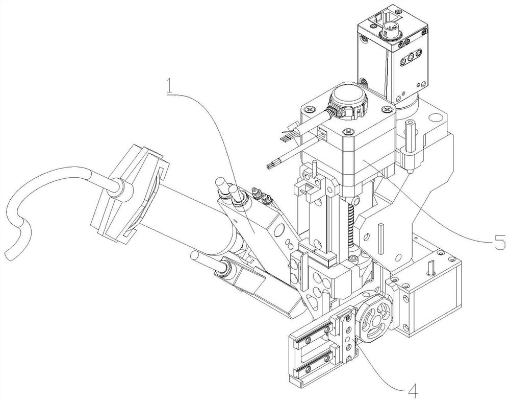
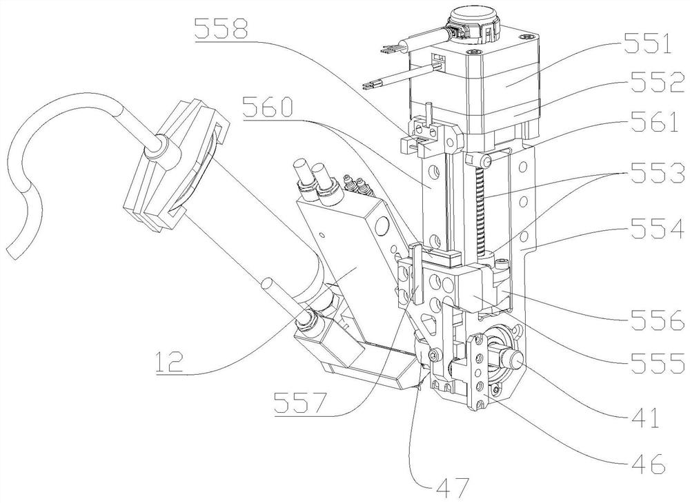
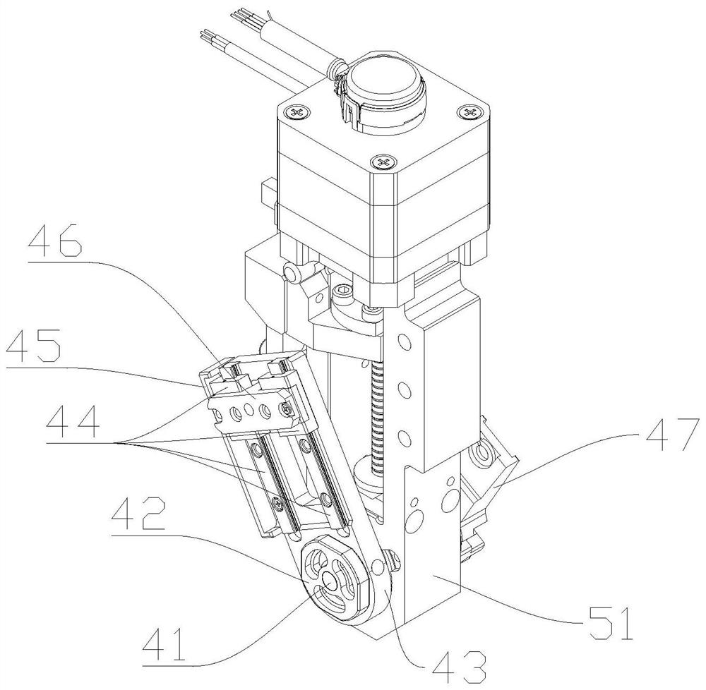
[0031] Please combine Figure 1 to Figure 5 , figure 1 is a schematic structural diagram of a dispensing device provided in an embodiment of the present application, figure 2 It is a partial structural schematic diagram of a dispensing device provided in an embodiment of the present application, image 3 It is a schematic diagram of the connection between the swing mechanism 4 and the drive ...


PUM


Abstract

The invention discloses a dispensing device, and belongs to the field of dispensing manufacturing. The dispensing device comprises a dispensing mechanism, a driving mechanism, a movable block, a follow-up block and a swing frame, wherein the movable block is connected with the driving mechanism; the driving mechanism is used for driving the movable block to reciprocate in the driving direction; one end of the follow-up block is hinged to the movable block; the other end of the follow-up block is connected to the swing frame in a sliding mode; the swing frame and the dispensing mechanism are both fixedly installed on the same rotating shaft; and when the follow-up block moves along with the movable block and slides relative to the swing frame, the swing frame and the dispensing mechanism can be driven to rotate around the rotating shaft at the same time. The problems that in the prior art, due to the fact that the inclination angle of a dispensing spray head is fixed and cannot easily meet the dispensing requirement of special-shaped coating faces such as a conical face and a curved face due to electronic product updating, and the dispensing effect is poor are solved; the dispensingrequirement of the special-shaped coating faces is met; and the dispensing effect is improved.

Description

technical field [0001] The invention belongs to the field of glue dispensing manufacturing, and relates to a glue dispensing device and glue dispensing equipment. Background technique [0002] With the continuous development of science and technology, a new generation of electronic packaging technology represented by surface mount technology has emerged. The fixing of electronic components is one of the core processes of surface mount. At present, the industry mainly uses dispensing equipment to bond and fix the components. The application of dispensing technology in electronic packaging technology came into being with the continuous updating and iteration of electronic products. [0003] At present, the inclination angle of the dispensing nozzle is fixed during the dispensing process, and the dispensing posture cannot be adjusted dynamically in time, and it is difficult to adapt to the dispensing requirements of special-shaped surfaces such as tapered surfaces and curved s...

Claims


Application Information

Patent Timeline
IPC IPC(8): B05C5/02B05C11/00B05C5/00
CPCB05C5/001B05C5/0208B05C11/00
Inventor 郜福亮史晔鑫胡君君苗虎曲东升李长峰
Owner CHANGZHOU MINGSEAL ROBOT TECH CO LTD
Learn More