Special turning tool with split type tool bars for machining train spoke plate

A train wheel, split-type technology, applied to the accessories of tool holders, metal processing equipment, tool holders, etc., can solve the problem of high cost of replacing tool holders, reduce the risk of damage to turning tool accessories, reduce replacement costs, and reduce production cost effect

Active Publication Date: 2021-01-29
奇锋金属科技有限公司
View PDF6 Cites 0 Cited by
  • Summary
  • Abstract
  • Description
  • Claims
  • Application Information

AI Technical Summary

Problems solved by technology

[0006] Aiming at the problem of the high cost of replacing the tool bar as a whole after the tool bar of the above-mentioned special turning tool for processing train wheel panels is damaged, the present invention provides a special turning tool for processing train wheel panels with a split tool bar, which adopts a detachable When the sub-tool bar is damaged, only the sub-tool bar can be replaced, which greatly reduces the cost of accessories compared with replacing the entire tool bar

Method used


Image

  • Special turning tool with split type tool bars for machining train spoke plate
  • Special turning tool with split type tool bars for machining train spoke plate
  • Special turning tool with split type tool bars for machining train spoke plate

Examples


Embodiment 1

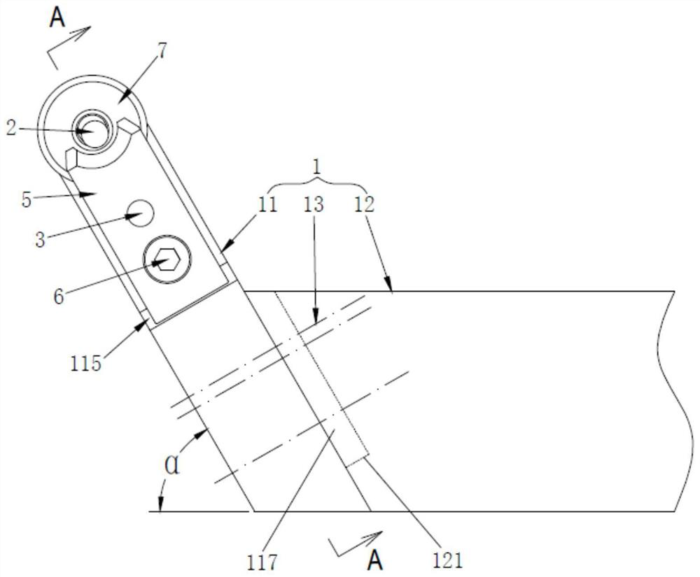
[0046] Such as figure 1 A special-purpose turning tool for train wheel panel processing with a split cutter bar shown in , includes a tool bar assembly 1 and a cutter body 7, and the tool bar assembly 1 includes a secondary tool bar 11 and a main tool bar 12 that are detachably connected together , the auxiliary cutter bar 11 is arranged at the front end of the main cutter bar 12 and extends obliquely to one side of the main cutter bar 12 , and the cutter body 7 is installed at the front end of the auxiliary cutter bar 11 . Due to the adoption of the detachable tool bar assembly 1, when the secondary tool bar 11 is damaged, only the secondary tool bar 11 can be replaced, which greatly reduces the replacement cost of accessories compared with the replacement of the entire tool bar.

[0047] Such as figure 1 and figure 2 As shown in , in this embodiment, the auxiliary cutter bar 11 and the main cutter bar 12 are fixedly connected by several long bolts 13 . In addition, in ...

Embodiment 2

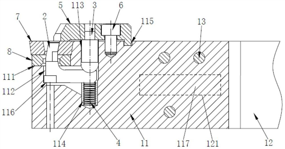
[0051]The special-purpose turning tool for train wheel panel processing in the present embodiment, the basic structure is the same as embodiment 1, and the differences and improvements are as follows: figure 2 As shown in , the special turning tool for processing train wheel webs also includes a check pin 2 , an ejector pin 3 , an elastic member 4 , a pressing block 5 and a tool shim 8 . Specifically:

[0052] The front end of the auxiliary knife rod 11 has a knife mounting groove 111 , and a cavity 112 is formed below the knife mounting groove 111 , and the cavity 112 is used to accommodate the hook pin 2 .

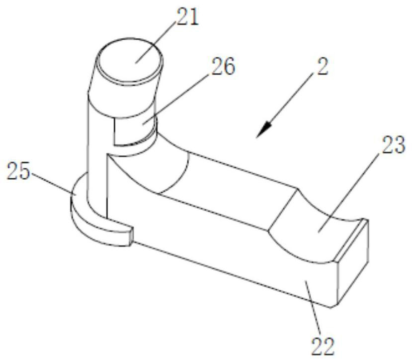
[0053] Such as image 3 As shown in , the hook pin 2 has a locking knife end 21 and a pressure end 22, the hook pin 2 is accommodated in the cavity 112, the pressure end 22 extends horizontally to the inside of the cavity 112, and the locking knife end 21 extends from the cavity 112 The upper mouth that is positioned at the middle part of knife-loading groove 111 stre...


PUM


Abstract

The invention discloses a special turning tool with split type tool bars for machining a train spoke plate, and relates to the field of turning tools. The special turning tool comprises a tool bar assembly and a tool body; the tool bar assembly comprises the auxiliary tool bar and the main tool bar, the auxiliary tool bar and the main tool bar are detachably connected together, and the auxiliary tool bar is arranged at the front end of the main tool bar and obliquely extends towards one side of the main tool bar; the tool body is mounted at the front end of the auxiliary tool bar; the auxiliary tool bar is fixedly connected with the main tool bar through a plurality of long bolts; and a positioning groove is formed in the front end of the main tool bar, a positioning inserting block matched with the positioning groove is arranged at the side, making contact with the front end of the main tool bar, of the auxiliary tool bar, and the positioning inserting block is inserted into the positioning groove. According to the special turning tool, the detachable tool bar assembly is adopted, after the auxiliary tool bar is damaged, only the auxiliary tool bar needs to be replaced, and compared with replacement of the whole tool bar, the accessory replacement cost is greatly reduced.

Description

technical field [0001] The invention relates to the field of turning tools, in particular to a special turning tool for processing train wheel panels with split tool bars. Background technique [0002] Turning is the most widely used processing method in the machine manufacturing industry. The tools used are mainly turning tools, which are suitable for machining rotary surfaces. Most workpieces with rotary surfaces can be processed by turning methods, such as inner and outer cylindrical surfaces, Internal and external conical surfaces, end faces, grooves, threads and rotary forming surfaces, etc. [0003] The rough machining of the surface of the railway spoke plate is done with turning tools. The web surface of a conventional train wheel has a gentle transition along its radial direction, which is relatively easy to process. Therefore, the traditional turning tool can be used to complete the process. However, for some train wheel test products with special structures, tra...

Claims


Application Information

Patent Timeline
Patent Type & Authority Applications(China)
IPC IPC(8): B23B29/04B23B27/00
CPCB23B29/04B23B27/00
Inventor 杨轩奇
Owner 奇锋金属科技有限公司
Why Eureka
Try Eureka