Theft deterrent tag

a technology of deterrent tags and lanyards, applied in the direction of protective materials radiating elements, lock applications, instruments, etc., can solve the problems of bending pins, affecting the insertion of lanyards, so as to prevent the defeat of the attaching mechanism, reduce labor time and costs, and reduce replacement costs

Inactive Publication Date: 2008-07-01
SAYEGH ADEL O +2
View PDF21 Cites 26 Cited by
  • Summary
  • Abstract
  • Description
  • Claims
  • Application Information

AI Technical Summary

Benefits of technology

[0017]In keeping with the principles of the present invention, a unique EAS theft deterrent tag is disclosed wherein the tag is capable of engaging articles that are to be monitored without necessitating the puncture of the articles with a pin. In addition, by providing a first and second half that are hingedly attached, labor time and costs are reduced when removing the tag from an article being protected thereby because separate bins are not required for the two halves. In addition, replacement costs are further reduced because the mates to the tags cannot be separated and lost.
[0018]In addition, the magnetic force necessary to disengaged the attaching mechanism of the tag is greater than required in the prior art ball and clutch mechanisms. Furthermore, the attaching mechanism of the instant invention provides a shock absorbing mechanism to prevent defeat of the attaching mechanism by the application of a strike force thereto by a blunt object.

Problems solved by technology

The hinged attachment may lead to the bending of the pin when contacting the locking component because of the predetermined arc that it must travel as a result of the hinged arrangement.
A drawback with existing lanyards is that they may be severed to remove the tag holder from the item of merchandise.
Some existing lanyards are difficult to assemble and require both ends of the lanyard to be held in alignment while the sharp tack of the holder is threaded through the ends of the lanyard.
However, such pin clutch mechanisms are defeated by sharply striking the tag with a tool, such as a hammer, which release the balls from engagement with the pin.
However, such devices may be defeated by simply cutting through the engaging member.
Furthermore, because the engaging member is detachable from the tag, it can be misplaced or lost by the user.
The prior art does not address the need for an EAS tag that is difficult to defeat and easy to use.
In addition, the prior art fails to provide a theft deterrent tag assembly that can be securely engaged to articles that cannot be penetrated by a pin.

Method used


Image

  • Theft deterrent tag
  • Theft deterrent tag
  • Theft deterrent tag

Examples


Embodiment Construction

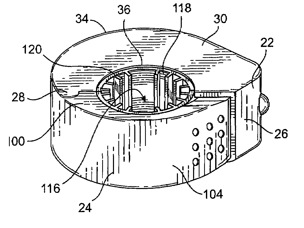
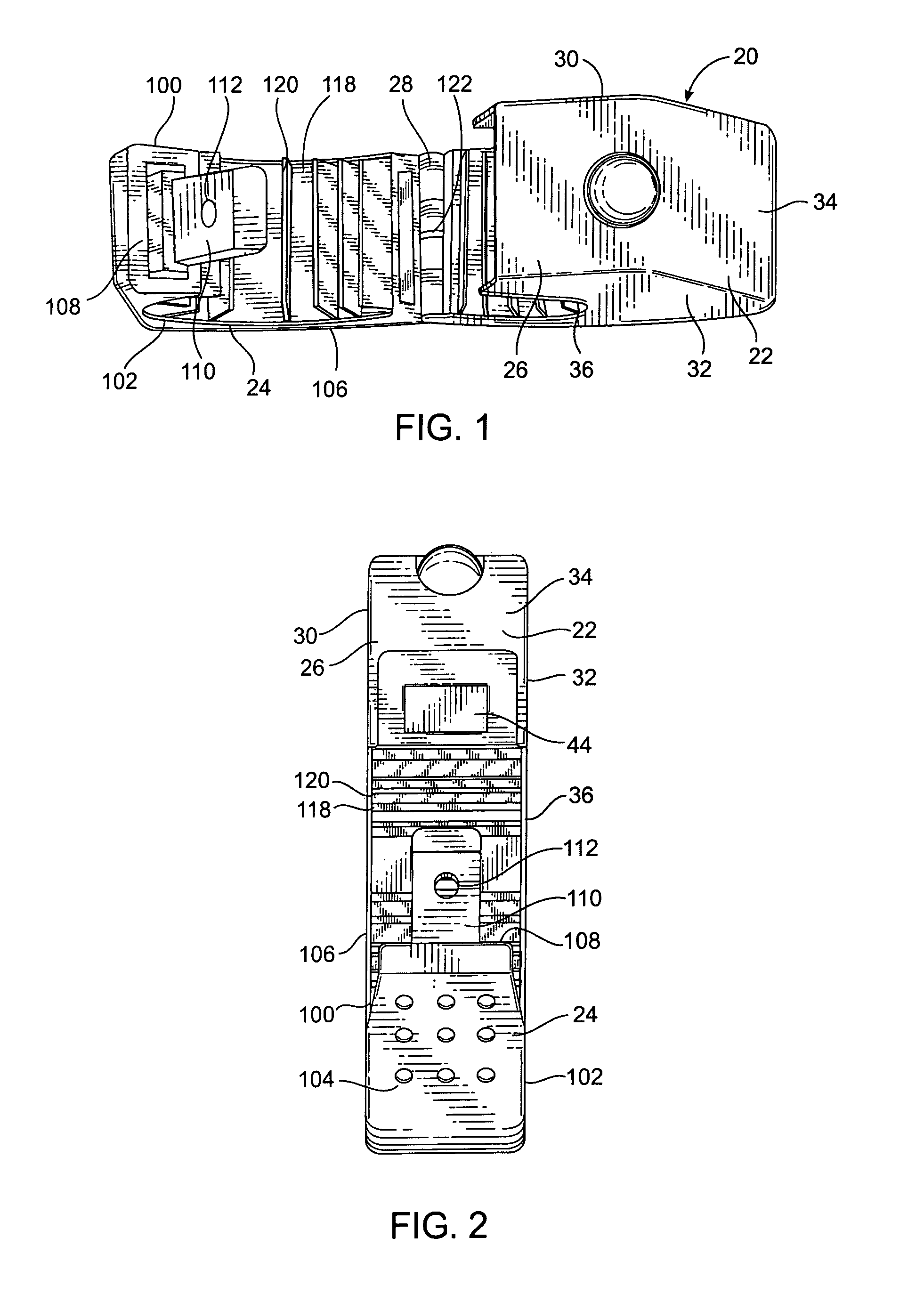
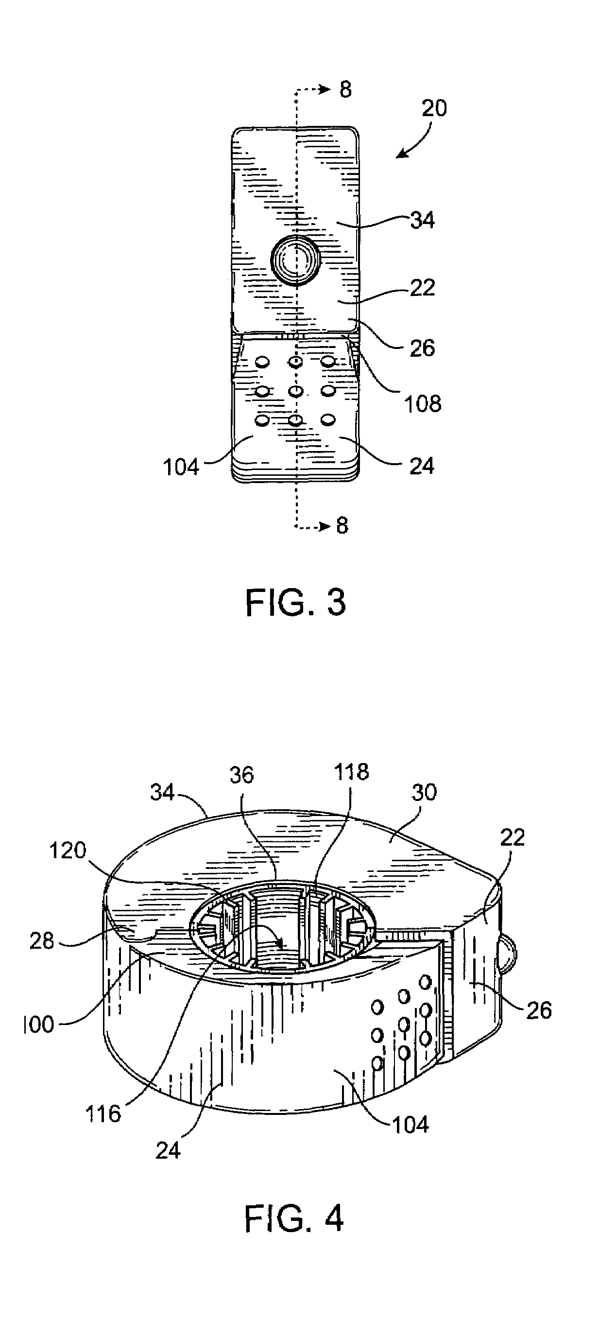
[0036]Referring now to FIGS. 1 through 4, a tag 20 is illustrated having a first half 22 and a second half 24. First and second halves 22 and 24 are preferably made of a hard or rigid material and are adapted to attach to one another and form a front end 26 and a rear end 28. A usable rigid or hard material might be a hard plastic such as, for purposes of illustration but not limitation, an injection molded ABS plastic. First and second halves 22 and 24 are hingedly attached at rear end 28 and are detachably attached at the front end 26 by an attaching means.

[0037]Now also referring to FIGS. 5 and 6, first half 22 has first left wall 30 and a first right wall 32 interconnected at the periphery thereof by a first outer wall 34 and a first inner wall 36, thereby a space is formed therebetween. In a preferred embodiment, ABS plastic material is used to make tag 20 whereby first left wall 30 and, first outer wall 34, and first inner wall 36 may be injection molded and then first right w...


PUM


Abstract

An article surveillance tag that has a shock absorbing mechanism that prevents unauthorized removal of the tag by the application of a strike force to the tag by a blunt object. In one embodiment, the article surveillance tag is adapted to engage articles that cannot be penetrated by pins.

Description

CROSS-REFERENCE TO RELATED APPLICATIONS[0001]The contents of this application are related to United States design patent applications titled “ELECTRONIC ARTICLE SURVEILLANCE TAG” and “ELECTRONIC ARTICLE SURVEILLANCE UNIT” having serial numbers 29 / 240,195 and 29 / 240,196, respectively, filed on Oct. 11, 2005, the contents of which are incorporated herein by reference.FIELD OF THE INVENTION[0002]The invention relates to theft deterrent security tags in general, and in particular to a security tag that is attachable to items to be monitored which items cannot be penetrated by a pin.BACKGROUND OF THE INVENTION[0003]Various types of electronic article surveillance (EAS) systems are known having the common feature of employing a marker or tag which is affixed to an article to be protected against theft from a controlled area, such as merchandise in a store. When a legitimate purchase of the article is made, the marker can either be removed from the article, or converted from an activated s...

Claims


Application Information

Patent Timeline
Patent Type & Authority Patents(United States)
IPC IPC(8): G08B13/14
CPCE05B73/0017G08B13/2434E05B73/0041
Inventor SAYEGH, ADEL O.LI, SHAOSHANSHANG, WEI
Owner SAYEGH ADEL O
Why Eureka
Try Eureka