Small plano-convex lens edge grinding and polishing equipment

A plano-convex lens, small technology, used in grinding/polishing equipment, metal processing equipment, machine tools suitable for grinding workpiece edges, etc. , to achieve the effect of accurate placement and avoid injury

Active Publication Date: 2021-01-29
SHAOYANG UNIV
View PDF6 Cites 11 Cited by
  • Summary
  • Abstract
  • Description
  • Claims
  • Application Information

AI Technical Summary

Problems solved by technology

[0004] In order to overcome the disadvantages that people need to rotate the small plano-convex lens continuously, which is cumbersome, low work efficiency, and a little careless, the human hand is easily injured by the machine. The technical problem of the present invention is: to provide a small Grinding and polishing the edge of the plano-convex lens is more convenient, high work efficiency, and a small plano-convex lens edge grinding and polishing equipment that is not easy to be injured by the machine

Method used


Image

  • Small plano-convex lens edge grinding and polishing equipment
  • Small plano-convex lens edge grinding and polishing equipment
  • Small plano-convex lens edge grinding and polishing equipment

Examples


Embodiment 1

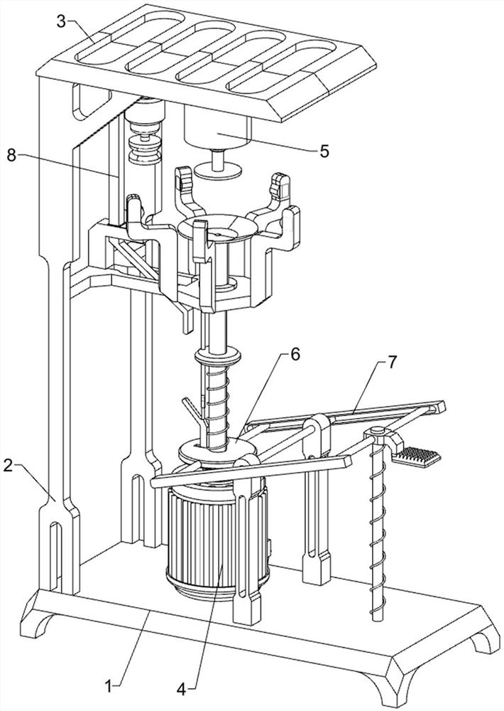
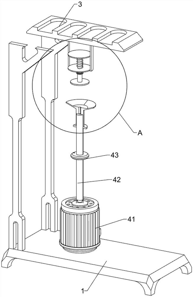
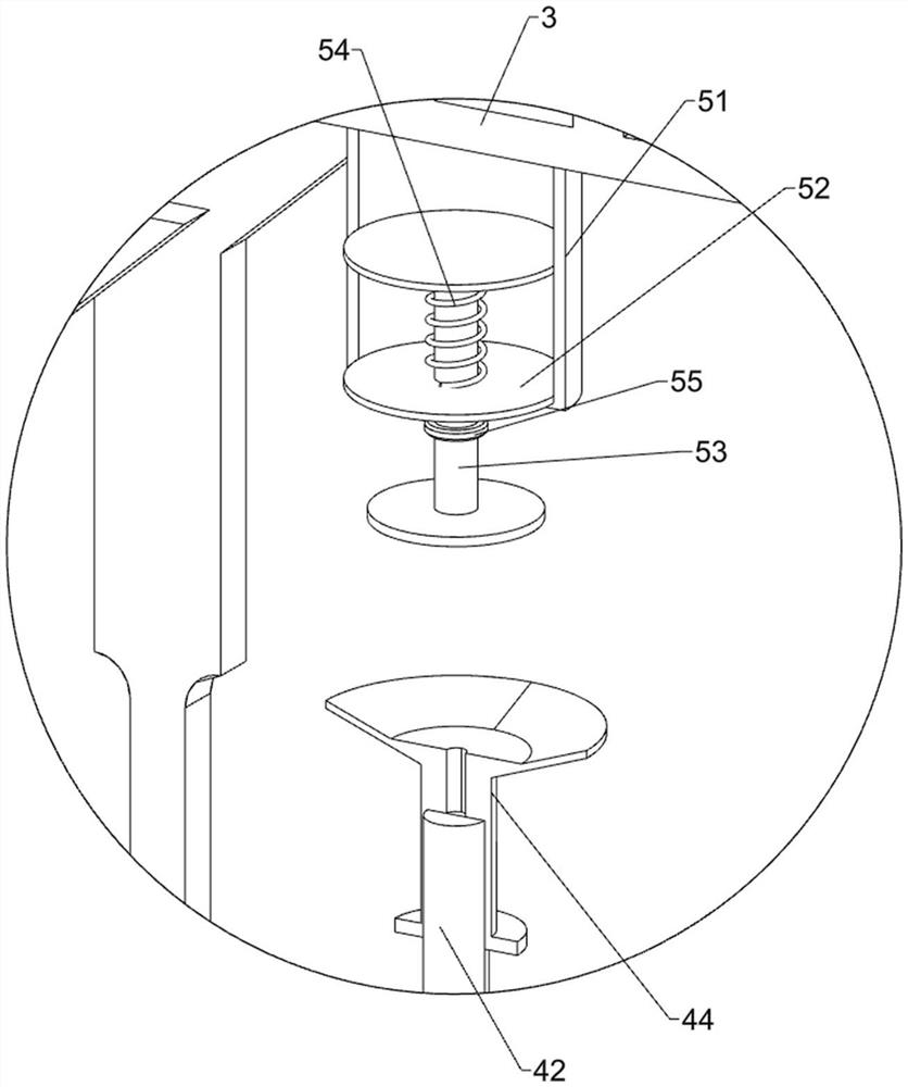
[0027] A small plano-convex lens edge grinding and polishing equipment, such as Figure 1-Figure 3 As shown, it includes a base 1, a first support rod 2, a support plate 3, a rotating assembly 4, and a clamping assembly 5. The left side of the top of the base 1 is fixed with the first support rod 2 symmetrically front and back, and the first support rods on the front and rear sides 2. A support plate 3 is fixedly connected between the top ends. A clamping assembly 5 is provided in the middle on the right side of the bottom of the support plate 3. A rotating assembly 4 is provided in the middle on the left side of the top of the base 1. The rotating assembly 4 cooperates with the clamping assembly 5.

[0028] The rotating assembly 4 includes a geared motor 41, a slide bar 42, a connection plate 43 and a suction cup 44. A geared motor 41 is installed in the middle of the left side of the top of the base 1. The output shaft of the geared motor 41 is slidably covered with a slide b...

Embodiment 2

[0034] On the basis of Example 1, such as figure 1 , Figure 4 , Figure 5 and Figure 7 As shown, an auxiliary limit assembly 6 is also included, and the auxiliary limit assembly 6 includes a sliding plate 61, a second spring 62, a first special-shaped limit rod 63, a fourth spring 64, a push rod 66, a mounting plate 67, a limit Bit cap 68, the fourth connecting rod 69 and the eighth spring 610, a mounting plate 67 is affixed between the top of the first support rod 2 inner side surfaces of the front and rear sides, the slide bar 42 runs through the middle of the right part of the mounting plate 67, and the mounting plate 67 right There is a push rod 66 slidingly connected between the middle of the part and the left part of the connection plate 43, the top of the push rod 66 is fixedly connected with the limit cap 68, the limit cap 68 is in contact with the bottom of the suction cup 44, and the bottom end of the push rod 66 is sliding. The fourth connecting rod 69 is place...

Embodiment 3

[0037] On the basis of embodiment 1 and embodiment 2, such as figure 1 , Figure 4 , Figure 6 and Figure 7 As shown, a power assembly 7 is also included, and the power assembly 7 includes a second support rod 71, a lever frame 72, a first connecting rod 73, a second connecting rod 74, a third connecting rod 75, a pedal 76 and a fifth spring 77. A second support rod 71 is fixedly connected to the front and back symmetrically in the middle of the top of the base 1, and the upper part of the second support rod 71 on the front and rear sides is rotatably connected with a prying frame 72, and the left parts of the front and rear sides of the prying frame 72 are all sliding The first connecting rod 73 is provided, and the inner ends of the first connecting rod 73 on the front and rear sides are fixedly connected with the outer circumferential direction of the sliding plate 61, and the middle of the right side of the top of the base 1 is fixedly connected with a second connecting...


PUM


Abstract

The invention relates to polishing equipment, in particular to small plano-convex lens edge grinding and polishing equipment. The small plano-convex lens edge grinding and polishing equipment can replace manual work to grind and polish the edge of a small plano-convex lens, is convenient and high in working efficiency, and hands are not prone to being injured by a machine. The small plano-convex lens edge grinding and polishing equipment comprises a base, and first supporting rods are symmetrically and fixedly connected to one side of the base. The small plano-convex lens is placed on a rotating assembly, the rotating assembly is pulled to drive the small plano-convex lens to move upwards to make contact with a clamping assembly, the clamping assembly is matched with the rotating assemblyto clamp and fix the small plano-convex lens, and the rotating assembly is started to drive the small plano-convex lens to rotate. A movable grinding tool makes contact with the small plano-convex lens to grind and polish the edge of the small plano-convex lens, so that the small plano-convex lens does not need to be held by hands, convenience is achieved, and the hands are prevented from being injured.

Description

technical field [0001] The invention relates to a polishing device, in particular to a small plano-convex lens edge grinding and polishing device. Background technique [0002] After the small plano-convex lens is made, the edge of the small plano-convex lens will be rough and have a lot of burrs, so the edge of the small plano-convex lens needs to be polished to make the small plano-convex lens convenient for subsequent processing. The machine cooperates with the grinding and polishing of the edge of the small plano-convex lens. First, start the grinding machine, and then hold the small plano-convex lens in contact with the grinding machine. The grinding mechanism will polish the edge of the small plano-convex lens. It is more comprehensive and requires people to continuously rotate the small plano-convex lens, which is troublesome, low in work efficiency, and a little careless, and people's hands are easily injured by the machine. [0003] Therefore, it is urgent to propo...

Claims


Application Information

Patent Timeline
Patent Type & Authority Applications(China)
IPC IPC(8): B24B9/14B24B41/06B24B27/00B24B41/02B24B47/12
CPCB24B9/14B24B9/146B24B27/0046B24B41/02B24B47/12
Inventor 肖小飞
Owner SHAOYANG UNIV
Why Eureka
Try Eureka