
Method for clearing wax in rod-pumped well

A technology of pumping wells and pumping units, which is applied in earthwork drilling, cleaning tools, wellbore/well components, etc., can solve problems such as reduced oil recovery rate, reduced oil recovery efficiency, and impact on production cycle, so as to avoid excessive injection rate. Fast or too slow, avoiding pump blockage and pump jamming, and improving economic benefits

Active Publication Date: 2021-01-29
PETROCHINA CO LTD
View PDF4 Cites 0 Cited by
  • Summary
  • Abstract
  • Description
  • Claims
  • Application Information

AI Technical Summary

Problems solved by technology

[0005] At present, when the rate of well-flushing fluid injection into the pumping unit well is too fast, the instantaneous flow pressure in the pumping unit well will be too high, and the well-flushing fluid will leak from the pumping unit well into the oil layer, causing pollution to the oil layer, resulting in well flushing Afterwards, a long recovery period is required to eliminate the pollution in the oil reservoir, which greatly reduces the oil recovery efficiency
When the injection rate of the well-washing fluid into the pumping unit well is too slow, the efficiency of cleaning the pumping unit well is low, which also affects the production cycle and reduces the oil recovery rate
At present, the general control injection time is 0.09m 3 / min, but it is still easy to pollute the oil layer in the pumping well, so it is very necessary to control the injection rate of the flushing fluid

Method used


Image

  • Method for clearing wax in rod-pumped well
  • Method for clearing wax in rod-pumped well
  • Method for clearing wax in rod-pumped well

Examples


Embodiment Construction

[0068] The principles and features of the present invention are described below, and the examples given are only used to explain the present invention, and are not intended to limit the scope of the present invention.

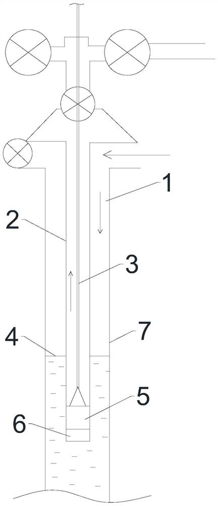
[0069] The structure of the pumping well is as figure 1 As shown, the pumping unit well includes an oil well and a pumping unit. The wellhead of the oil well is provided with an electric submersible pump, and the electric submersible pump is used to collect well-washing fluid from the formation and inject it into the oil well. The pumping unit specifically includes a casing 7, a pumping pump 5. The oil suction pipe 2 and the sucker rod 3, the oil suction pipe 2 is placed in the casing 7, the outer wall of the oil suction pipe 2 and the inner wall of the casing 7 form an oil casing annulus 1, and the oil well pump 5 is located in the casing 7, and The bottom end of the oil pipe 2 is fixedly connected, the pump inlet 6 of the oil well pump 5 faces vertically down...


PUM


Abstract

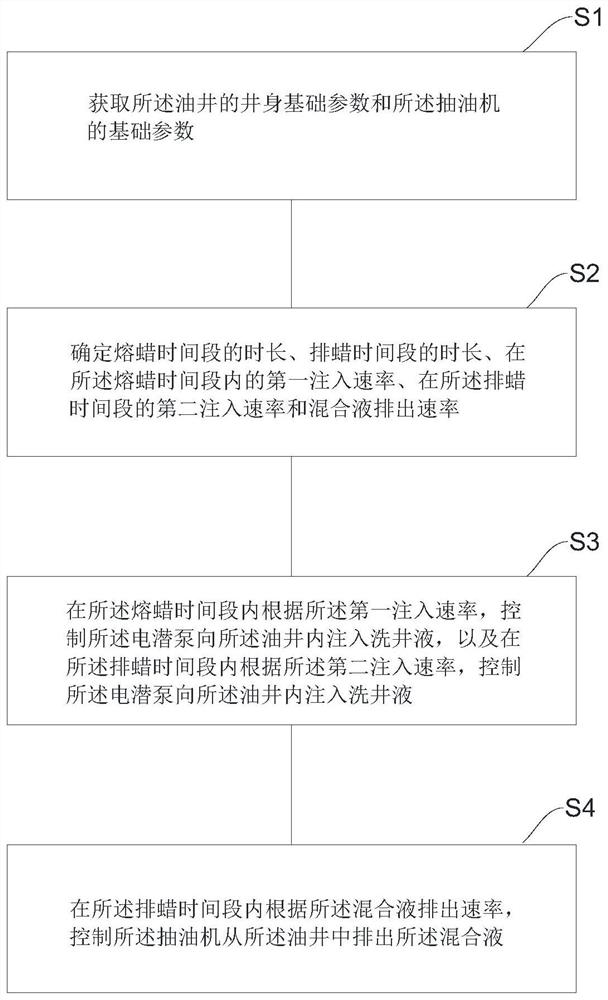
The invention relates to a method for clearing wax in a rod-pumped well, and belongs to the technical field of oil field oil extraction. The method comprises the steps that well bore basic parametersof an oil well and basic parameters of a pumping unit are obtained; according to the well bore basic parameters of the oil well and the basic parameters of the oil pumping unit, the duration of a waxmelting time period, the duration of a wax discharging time period, a first injection rate in the wax melting time period, a second injection rate and a mixed liquid discharging rate are determined inthe wax discharging time period; an electric submersible pump is controlled to inject flushing fluid into the oil well according to the first injection rate in the wax melting time period, and the electric submersible pump is controlled to inject the flushing fluid into the oil well according to the second injection rate in the wax discharging time period; and the pumping unit is controlled to discharge mixed liquid from the oil well according to the mixed liquid discharging rate in the wax discharging time period. The method has the beneficial effects that the recovery period after well washing can be shortened, and the phenomena of pump blockage and pump clamping caused by wax are avoided.

Description

technical field [0001] The invention belongs to the technical field of oil recovery in oil fields, and in particular relates to a method for cleaning wax in a pumping well. Background technique [0002] The pumping unit well includes an oil well and a pumping unit, the pumping unit includes a sucking pipe, a sucker rod is arranged in the sucking pipe, and a pump is installed at the bottom of the sucking pipe, the parts of the sucking pipe and the sucking rod are located in the oil well, and the pumping pump located in the oil well. During the normal operation of the pumping well, since the crude oil contains wax, as the crude oil is lifted up by the pump from the bottom of the well, the temperature and pressure of the crude oil will drop accordingly, and the wax will be on the well wall of the oil well and Crystallization occurs on the wall of the pumping pipe, the pump, and the sucker rod. After the wax crystallizes, it will have a great impact on the production indicators...

Claims


Application Information

Patent Timeline
Patent Type & Authority Applications(China)
IPC IPC(8): E21B37/06
CPCE21B37/06Y02E10/10
Inventor 赵常明冯峰王世谦王真夏瑛宁鹤飞杨秀军杨恩波李智
Owner PETROCHINA CO LTD
Learn More