
An s-parameter adjustable radio frequency connector

A technology for radio frequency connectors and parameters, which is applied in the directions of antenna connectors, connections, and conductive connections. It can solve the problems of high probability of deterioration of antenna intermodulation indicators and the inability to debug S parameters, so as to achieve good welding effect and improve antenna intermodulation. The effect of leveling and regulating process stability

Active Publication Date: 2022-07-08
COMBA TELECOM TECH (GUANGZHOU) CO LTD +1
View PDF0 Cites 0 Cited by
  • Summary
  • Abstract
  • Description
  • Claims
  • Application Information

AI Technical Summary

Problems solved by technology

[0003] The present invention aims to overcome the defects of the above-mentioned prior art that the S parameters cannot be debugged and the antenna intermodulation index has a high probability of deterioration, and provides a radio frequency connector with adjustable S parameters, which is used to realize that the S parameters of the radio frequency connector can be debugged, Realize the direct connection between the RF connector and the antenna input port through the cable, thereby eliminating the need for additional connectors at the main feeder end, reducing 3 additional solder joints at the main feeder end with the highest current density, and improving the antenna intermodulation index

Method used


Image

  • An s-parameter adjustable radio frequency connector
  • An s-parameter adjustable radio frequency connector
  • An s-parameter adjustable radio frequency connector

Examples


Embodiment 1

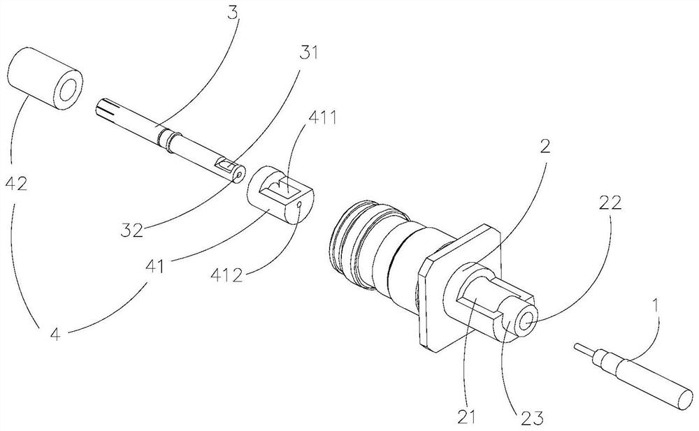
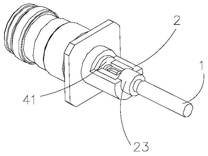
[0025] like figure 1 As shown, this embodiment provides an S-parameter adjustable radio frequency connector. The radio frequency connector includes an outer conductor 2 , an inner conductor 3 and an insulating support 4 .

[0026] In order to facilitate understanding of the S-parameter adjustable radio frequency connector provided by the embodiment of the present application, an application scenario of the S-parameter adjustable radio frequency connector is first described below. The radio frequency connector described in the embodiment of the present application is applied to the base station antenna, and is used for connecting with the coaxial cable 1 so as to be directly connected to the antenna. In the RF connector, the inner conductor 3 and the coaxial cable 1 are connected by welding the inner conductor 3 and the coaxial cable 1 . The outer conductor 2 provides a space for accommodating the inner conductor 3 . Since both the outer conductor 2 and the inner conductor 3 ...

Embodiment 2

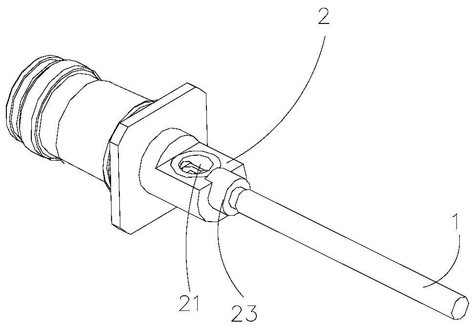
[0036] like image 3As shown, Embodiment 2 provides an S-parameter adjustable radio frequency connector, the radio frequency connector includes an outer conductor 2 , an inner conductor 3 , and an insulating support 4 . The general configuration of the radio frequency connector of this embodiment is basically the same as that of Embodiment 1, and the difference from Embodiment 1 is that the opening window 21 is circular.

Embodiment 3

[0038] like Figure 4 As shown, Embodiment 3 provides an S-parameter adjustable radio frequency connector, and the radio frequency connector includes an outer conductor 2 , an inner conductor 3 , and an insulating support 4 . The general configuration of the RF connector of this embodiment is basically the same as that of Embodiment 1. The difference from Embodiment 1 is that the RF connector of this embodiment is a through-wall RF connector, and the length of the coaxial cable 1 is longer than that of Embodiment 1. long. The outer conductor 2 further includes a flange 24 , a locking nut 25 and a thread 26 . The flange 24 , the locking nut 25 and the thread 26 are sequentially arranged at one end of the opening window 21 away from the protruding portion 23 . In specific use, the outer conductor 2 is inserted into the end cover of the antenna through the thread 26, and the flange 24 does not pass through the end cover of the antenna. At this time, the RF connector is locked on...


PUM


Abstract

The present invention provides an S-parameter adjustable radio frequency connector, which includes an outer conductor, wherein the shaft is provided with a cavity, and an open window is provided on the outer wall thereof. The inner conductor is inserted into the cavity of the outer conductor, and is butted with the coaxial cable at the open window, and a certain amount of solder is used to weld the coaxial cable and the coaxial cable. the inner conductor to adjust the S-parameter of the radio frequency connector. The radio frequency connector of the present invention can be welded more stably, so that the welding effect is better, and the actual amount of the solder can be better controlled. Moreover, after the coaxial cable is connected with the RF connector, it is directly connected to the antenna input port, which not only eliminates the main feeder connector, but also maintains the adjustable S parameter of the main feeder; it eliminates the main feeder connector and saves material costs. At the same time as the assembler, three solder joints are reduced at the main feed end with the largest current density, which greatly improves the level of antenna intermodulation.

Description

technical field [0001] The invention relates to the field of radio frequency connectors, and more particularly, to a radio frequency connector with adjustable S-parameters. Background technique [0002] For existing RF connectors, such as 7 / 16Din and 4.3-10 RF connectors in the field of base station antennas, the outer conductor of the connector completely wraps the inner conductor of the connector. After the connector is made, the connector is a closed part, and S-parameters cannot be debugged. At the same time, in the actual production of the antenna, the connection between the RF connector and the antenna input port of the base station is usually connected by a connector with S-parameter debugging function, and this connector can cooperate with the S-parameter. Specifically, the connector introduces three additional solder joints at the main feed end with the largest current density. However, the increase of solder joints at the main feed end greatly increases the probab...

Claims


Application Information

Patent Timeline
Patent Type & Authority Patents(China)
IPC IPC(8): H01R9/05H01R4/02H01R24/40
CPCH01R9/05H01R4/023H01R24/40H01R2201/02
Inventor 陈汝承贾飞飞王强宋欢林张鑫桢杨长城
Owner COMBA TELECOM TECH (GUANGZHOU) CO LTD
Learn More