
On-site marking system for cable body

A cable body and cable technology, applied in the field of cable body on-site marking system, can solve problems such as increasing labor force and reducing construction work efficiency, and achieve the effect of reducing construction labor intensity

Active Publication Date: 2022-06-24
STATE GRID CHONGQING ELECTRIC POWER +1
View PDF0 Cites 1 Cited by
  • Summary
  • Abstract
  • Description
  • Claims
  • Application Information

AI Technical Summary

Problems solved by technology

However, the actual construction site currently does not have a conveying and marking system that can transport cables at the same time and mark them at a fixed distance. Most cables are marked artificially, which increases the labor force and reduces the efficiency of construction operations.

Method used


Image

  • On-site marking system for cable body
  • On-site marking system for cable body
  • On-site marking system for cable body

Examples


Embodiment

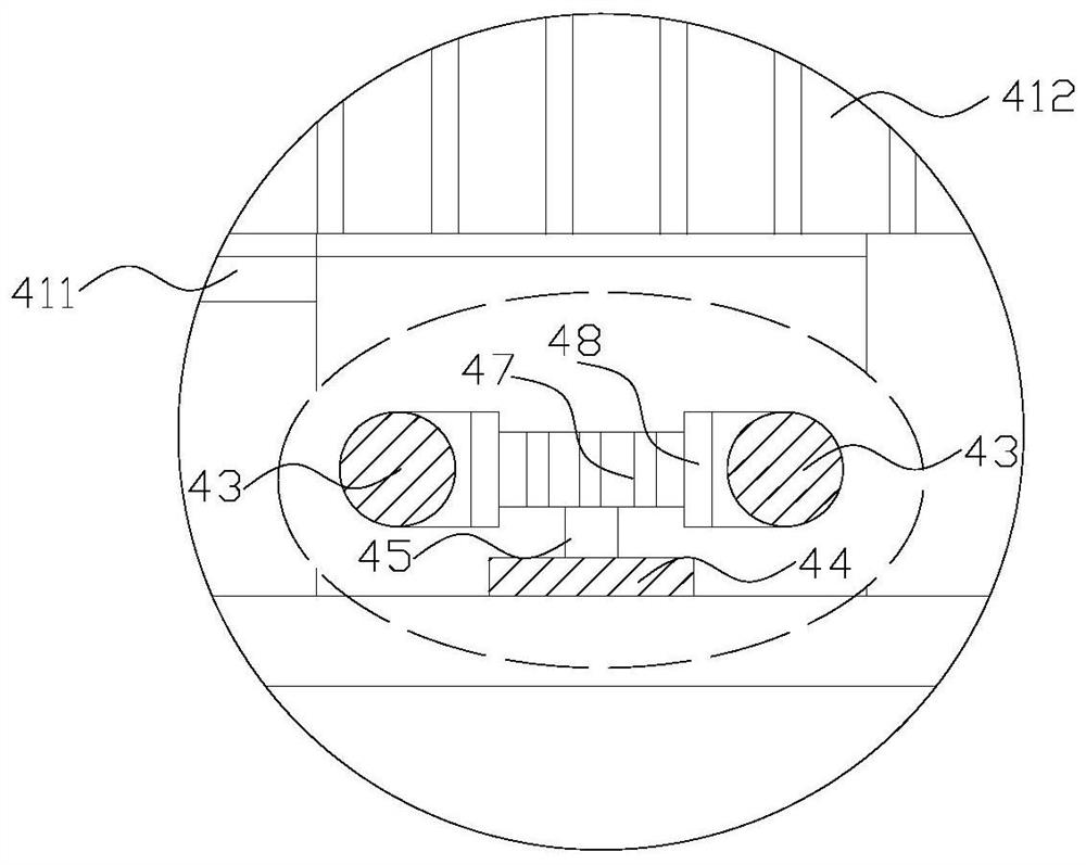
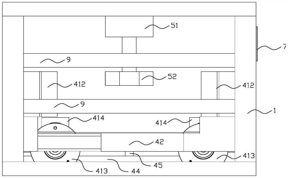
[0051] like Figure 1 to Figure 6 As shown, the cable body field marking system includes,

[0052] rack 1;

[0053] The forward guiding unit 2 is arranged on one end of the rack 1; the cable is limited and guided;

[0054] The rearward guiding unit 3 is arranged on the rack 1 and is opposite to the forward guiding unit 2;

[0055] The pulling unit is arranged in the middle of the frame 1, facing the forward guiding unit 2, and transports the cables from the forward guiding unit 2 to the rearward guiding unit 3;

[0056] The marking unit, which is arranged on the frame 1 and located in the rearward guiding unit 3 , marks the cables passing through the rearward guiding unit 3 .

[0057] The structure of this embodiment is simple, the cable can be transported at the cable construction site, the construction labor intensity is reduced, and the cable can be marked during the transport process to realize the identification of the cable.

[0058] In this embodiment, the front gui...


PUM


Abstract

The invention discloses an on-site marking system for a cable body, which comprises a frame; a forward guiding unit arranged on one end of the The units are opposite; the traction unit is set in the middle of the frame, facing the forward guiding unit, and transports the cables from the forward guiding unit to the backward guiding unit; the marking unit is set on the frame and is located in the backward guiding unit. Mark the cable that passes through the rear-guiding unit. The invention can synchronously transport and mark the cables during the process of setting out and wiring, and can greatly reduce the labor intensity of construction operations.

Description

technical field [0001] The invention relates to the field of cables, in particular to a cable body on-site marking system. Background technique [0002] With the continuous development of the power grid, new power grid contexts are constantly being created, and a large number of cables are placed inside the cable channel. In addition, it is difficult to distinguish between maintenance and repair in the future. Cable printers can print on cables of different specifications, and can Print all kinds of information of the re-wired on the cable body, which is beneficial to electric power repair, emergency rescue and maintenance in the future, and reduces the time for cable search and identification. [0003] The existing equipment for cable body marking at home and abroad mainly include laser marking machine, ink spraying machine, ink spraying machine, etc. However, their operating environment is generally in the workshop, which is less affected by the environment. However, the ...

Claims


Application Information

Patent Timeline
Patent Type & Authority Patents(China)
IPC IPC(8): H01B13/34
CPCH01B13/34
Inventor 冯德伦夏荣魏林吴文勤肖霖邱创黄文谦王梅黄加一刘恒王幸张曦艾洪康昊天何剑楠
Owner STATE GRID CHONGQING ELECTRIC POWER
Learn More