[0024]The technical solutions in the embodiments of the present invention will be clearly and completely described below in conjunction with the accompanying drawings in the embodiments of the present invention. Obviously, the described embodiments are only a part of the embodiments of the present invention, rather than all the embodiments. Based on the embodiments of the present invention, all other embodiments obtained by those of ordinary skill in the art without creative work shall fall within the protection scope of the present invention.
[0025]It should be noted that if there are directional indications (such as up, down, left, right, front, back...) in the embodiment of the present invention, they are only used to explain the relationship between components in a particular posture. If the specific posture changes, the directional indication will also change accordingly.
[0026]In addition, if the descriptions of "first", "second", etc. are involved in the present invention, they are only used for descriptive purposes, and cannot be understood as indicating or implying their relative importance or implicitly specifying the indicated technical features. Quantity. Therefore, the features defined with "first" and "second" may explicitly or implicitly include at least one of the features. In addition, the technical solutions between the various embodiments can be combined with each other, but they must be based on what can be achieved by those of ordinary skill in the art. When the combination of technical solutions is contradictory or cannot be achieved, it should be considered that such a combination of technical solutions does not exist. , Is not within the protection scope of the present invention.
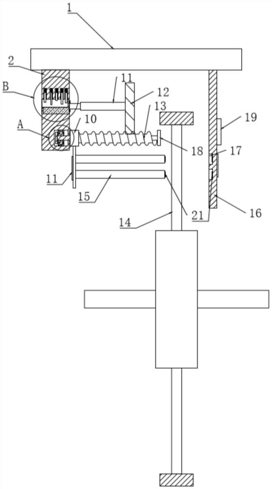
[0027]SeeFigure 1~5In an embodiment of the present invention, an anti-theft device for an electric vehicle includes a mounting plate 1 mounted on the vehicle body above the wheels of the electric vehicle; and a lock body for clamping the hub 14 mounted on the wheel of the electric vehicle Inside, the lock body includes a base 2 and a fixing plate 16. The base 2 and the fixing plate 16 are fixedly installed at the bottom of the mounting plate 1. The base 2 and the fixing plate 16 are located on both sides of the hub 14. 2 is installed inside the lock core 6 and the fixing member 5 that cooperate with each other. The bottom outer wall of the lock core 6 is fixedly connected with the helical gear 12 through the connecting rod 11, and the screw rod 13 engaged with the helical gear 12 is provided under the helical gear 12, so The screw 13 is rotatably installed at the bottom of the base 2, and a moving block 10 is sleeved on the screw 13, and the moving block 10 is provided with threads that cooperate with the screw 13, and the bottom of the moving block 10 is fixedly installed A movable plate, a plurality of lock rods 15 parallel to the screw rods are fixedly installed on the movable plate, a connecting groove 17 is provided on the opposite side of the fixed plate 16 and the movable plate, and the connecting groove 17 is movable with the lock rod 15 connection.
[0028]In this embodiment, when the device is not locked, the lock lever 15 is separated from the connecting groove 17. At this time, the moving block 10 is far away from the bottom of the helical gear 12 and is attached to the side wall of the base 2. When the electric vehicle is not used, use the key Insert into the lock cylinder 6, the lock cylinder 6 is separated from the fixed part 5, turn the key, drive the lock cylinder 6 to rotate, because the helical gear 12 is fixedly installed at the axis position of the lock cylinder 6 through the connecting rod 11, it will drive the tilt The gear 12 rotates, thereby driving the screw rod 13 that is matched with the helical gear 12 to rotate, the moving block 10 sleeved on the screw rod 13 approaches the helical gear 12, and drives the lock rod 15 on the moving plate to move to the connecting plate 16 until the lock is locked. The top end of the rod 15 passes through the hub 14 and is inserted into the connecting groove 17, pull out the key, and the lock core 6 is fitted and fixed with the fixing member 5. At this time, the helical gear 12 is fixed and no longer rotates, and the wheel hub 14 of the electric vehicle can be locked To prevent the electric vehicle from being stolen, in this embodiment, limit blocks are provided on both sides of the moving block 10 to prevent the moving block 10 from rotating.
[0029]In summary, use the key to turn the lock cylinder 6 and the lock cylinder 6 drives the helical gear 12 to rotate. The screw 13 and the moving block 10 drive the multiple lock rods 15 on the moving plate to move until the top of the lock rod 15 passes through the hub 14 and Insert it into the connecting slot 17, and then pull out the key to facilitate the lock rod 15 to pass through the hub 14 on the wheel of the electric vehicle to block the hub 14 to prevent the hub 14 from rotating and prevent the electric vehicle from being stolen. By using the helical gear 12 and the screw 13 meshing transmission, compared with the traditional electric vehicle lock, the structure is more stable, it can prevent the lock rod 15 from separating from the connecting groove 17, and the operation is simple. It can be realized only by turning the key, and it can be applied to various vehicle anti-theft.
[0030]SeeFigure 1~5As a preferred embodiment of the present invention, a deformation sensor 22 is installed on both the movable plate and the fixed plate 16, the fixed plate 16 is also provided with an alarm 19, the top end of the lock rod 15 and the connecting groove 17 Equipped with mutually corresponding wiring posts and wiring slots.
[0031]In this embodiment, the alarm 19 and the deformation sensor 22 on the fixed board 16 are kept energized with the battery. When the device is unlocked, the deformation sensor 22 on the moving board is kept in a power-off state. The connection posts and connection slots are set to make When the lock lever 15 is inserted into the connecting slot 17, the connecting column is connected to the connecting slot, and the deformation sensor 22 on the moving plate is energized. When someone vigorously shakes the moving plate and the fixed plate 16, the moving plate and the fixed plate 16 will deform. The deformation sensor 22 will send a signal to the alarm 19 after detecting the deformation of the moving plate or the fixed plate 16, and then the alarm 19 will send an alarm signal to the mobile phone for alarm. In this embodiment, the deformation sensor 22 sends a deformation signal, an alarm 19 Sending an alarm signal to a mobile phone belongs to the prior art, and it will not be described too much.
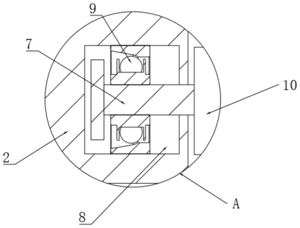
[0032]Seefigure 1 As a preferred embodiment of the present invention, one end of the screw rod 13 is fixedly connected with a rotating column 7, and the other end of the screw rod 13 is fixedly installed with a stopper 18, and the rotating column 7 is mounted on a base through a bearing 9. On the rotating slot 8 in 2, a stopper 18 is fixedly installed on the rotating column 7 near the port at the bottom of the rotating slot 8.
[0033]In this embodiment, the stopper 18 is provided to play a limiting role, which can prevent the screw rod 13 from being separated from the rotating groove 8 and the helical gear 12 when rotating. By providing the bearing 9 and the rotating column 7, the rotation of the screw rod 13 can be reduced. The friction force can also keep the screw rod 13 meshed with the helical gear 12 and prevent the screw rod 13 from tilting.
[0034]Seefigure 1 As a preferred embodiment of the present invention, the top of the lock rod 15 and the connecting groove 17 are also provided with magnets 21 with different magnetic poles.
[0035]In this embodiment, by arranging the magnet 21, the top box connecting groove 17 of the lock rod 15 can be tightly attracted to make the connection between the terminal and the connecting groove stable, and to ensure that the deformation sensor 22 on the moving board is energized and stable.
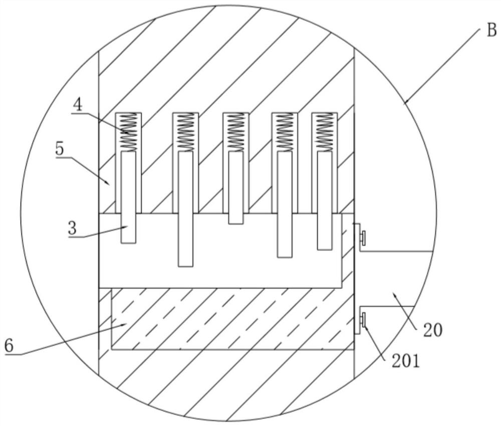
[0036]Seeimage 3 As a preferred embodiment of the present invention, the base 2 is provided with a mounting groove in the middle, and a fixing member 5 is fixedly installed in the mounting groove. The fixing member 5 has a cylindrical structure. A plurality of vertically downward moving grooves are arranged in the wall, and a plurality of lock keys 3 are arranged in the moving groove. The lock keys 3 are connected to the inner wall of the top of the moving groove by a spring 4, and the fixing member 5 rotates in the barrel A lock core 6 is installed, and the lock core 6 is provided with a card slot matched with the lock key 3.
[0037]In this embodiment, in the initial state, the lock key 3 naturally sags due to its own gravity, and the bottom of the lock key 3 is stuck into the card slot on the lock cylinder 6. At this time, the lock cylinder 6 and the fixing member 5 cannot rotate relative to each other. When the key is inserted When the card slot in the lock cylinder 6, the key pushes the lock key 3 back into the moving slot, so that the lock cylinder 6 and the fixing member 5 can rotate relative to each other. Turn the key to drive the lock cylinder 6 to rotate. In this embodiment, the lock There are two opposite card slots on the core 6, after turning the angle of the lock core 180 degrees, pull out the key, the lock key 3 will fall back into the card slot, and the lock rod 15 just inserted into the connecting slot 17 to complete the lock , The lock core 6 and the fixing part 5 are selected as the unlocking parts of the device, which is convenient for operation and not easy to be damaged.
[0038]Seeimage 3 As a preferred embodiment of the present invention, the connecting rod 11 is fixedly connected to the outer wall of the bottom of the lock cylinder 6 through a connecting seat 20, and both ends of the connecting seat 20 are connected to the connecting rod 11 and the bottom of the lock cylinder 6 through screws 201. The outer wall is fixed.
[0039]In this embodiment, the diameter of the lock cylinder 6 is smaller than the diameter of the connecting rod 11 in this embodiment, and the connecting seat 20 is used to connect the lock cylinder 6 and the connecting rod 11 to increase its applicability.
[0040]Preferably, the deformation sensor 22 is also electrically connected to the lights and horns of the electric vehicle. When the deformation sensor 22 detects that the moving plate or the fixed plate 16 is deformed, the lights of the electric vehicle will flash and the horn will sound an alarm. , Can remind the owner in time.
[0041]For those skilled in the art, it is obvious that the present invention is not limited to the details of the foregoing exemplary embodiments, and the present invention can be implemented in other specific forms without departing from the spirit or basic characteristics of the present invention. Therefore, from any point of view, the embodiments should be regarded as exemplary and non-limiting. The scope of the present invention is defined by the appended claims rather than the foregoing description, and therefore it is intended to fall within the claims. All changes within the meaning and scope of the equivalent elements of are included in the present invention. Any reference signs in the claims should not be regarded as limiting the claims involved.
[0042]In addition, it should be understood that although this specification is described in accordance with the implementation manners, not each implementation manner only includes an independent technical solution. This narration in the specification is only for clarity, and those skilled in the art should consider the specification as a whole The technical solutions in the embodiments can also be appropriately combined to form other implementations that can be understood by those skilled in the art.