A cam lathe numerical control system

A numerical control system and cam technology, applied in the general control system, control/regulation system, digital control, etc., can solve the problems of time-consuming and labor-intensive change, small equipment investment, poor processing accuracy, etc., to improve the economic benefits of enterprises and equipment investment Small, the effect of reducing input costs

Active Publication Date: 2021-06-25
荆州环球汽车零部件制造有限公司
View PDF6 Cites 0 Cited by
  • Summary
  • Abstract
  • Description
  • Claims
  • Application Information

AI Technical Summary

Problems solved by technology

The CNC milling machine has high machining accuracy, but the equipment investment is large, and the milling cutter consumes a lot; the profiling cam lathe has a small equipment investment, a small turning tool consumption, and high efficiency, but the machining accuracy is poor, requiring a grinding machine for additional processing, and it is time-consuming and laborious to change the model.

Method used


Image

  • A cam lathe numerical control system
  • A cam lathe numerical control system
  • A cam lathe numerical control system

Examples


Embodiment 1

[0031] Embodiment 1: The present invention provides a numerical control system for a cam lathe, including a cam lathe and a numerical control system.

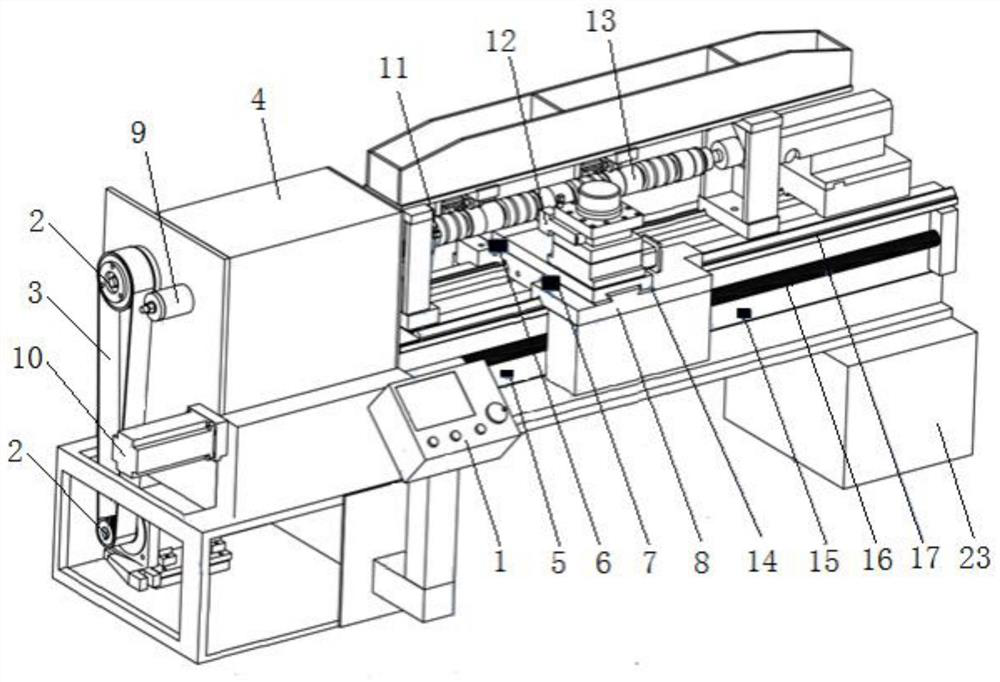
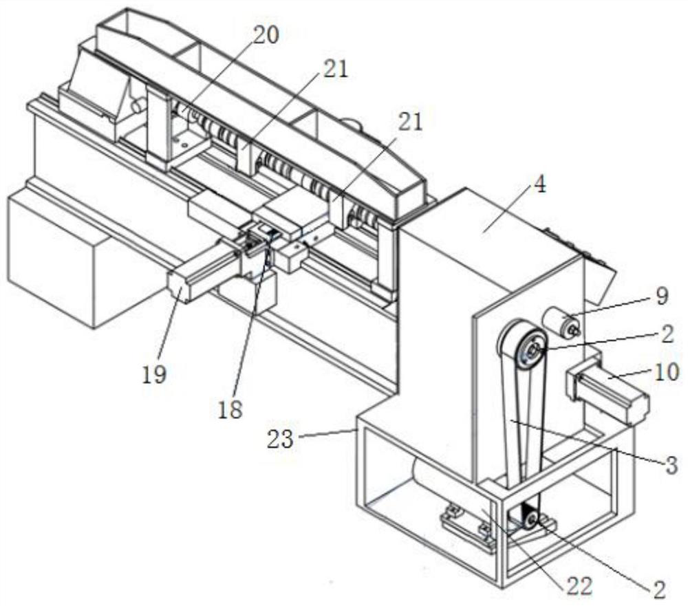
[0032] The structure of the cam lathe is as figure 1 ,2 shown. The cam lathe is provided with a frame 23, a gear box 4, an operating table 1, a headstock direct-coupled encoder 9, an X-axis servo motor 19, a Z-axis servo motor 10, a turning tool 12 and a headstock variable frequency motor 22; One side is provided with a gear box 4, and the outer side of the gear box is equipped with a synchronous wheel 2, a synchronous belt 3, a head frame direct-connected encoder 9 and a Z-axis servo motor 10, and a head frame variable frequency motor 22 is installed under the gear box, and the head frame variable frequency motor The head frame 11 is connected through the transmission mechanism in the synchronous wheel 2, the synchronous belt 3, and the gear box. The console 1 is installed in front of the gear box; Transmission screw 18, the...

Embodiment 2

[0057] Embodiment 2: use the cam lathe numerical control system processing cam of embodiment 1 of the present invention, the specific operation process is:

[0058] 1. First complete the writing of data.xlsx and processing.xlsx files:

[0059]In the present invention, the numerical control system of the cam lathe will use two files for each cam product, one for data.xlsx, and the other for processing.xlsx; Figure 6 and Figure 7 surface.

[0060] ⑴. According to the cam to be processed, the type of the cam to be processed is distinguished, and the parameters related to the workpiece are extracted from the product diagram;

[0061] ⑵. Open the data.xlsx electronic form in the host computer ( Figure 6 table) file:

[0062] a: Convert the lift data of the three types of cams in the product diagram into electronic cam data and fill them in respectively Figure 6 In the table, in columns A to C, rows 1 to 360, fill in column A for the exhaust cam, column B for the intake cam...


PUM


Abstract

The invention relates to a numerical control system for a cam lathe, comprising a cam lathe and a numerical control system. The cam lathe is provided with a frame, a gear box, an operating table, X-axis and Z-axis servo motors, a headstock frequency conversion motor and a cutting tool; the numerical control system is provided with Upper computer, PLC, synchronous X-axis, Z-axis motor servo driver and head frame motor inverter driver; use an industrial tablet computer as the upper computer, the upper computer is equipped with cam lathe processing software, the upper computer controls the PLC through RS232 serial port communication, and the PLC accepts The upper computer outputs motion parameters and motion commands, and the PLC uses the electronic cam function module to control the X-axis and the headstock direct-connected encoder to follow up, and controls the tool to complete the turning processing cam. The cam lathe in this numerical control system can be switched between two modes of automatic and manual processing; the numerical control system software of the present invention has a friendly interface and is easy to operate. The cam lathe has a small investment, less tool consumption, good machining accuracy, high efficiency and easy changeover easy.

Description

technical field [0001] The invention relates to a numerical control system of a cam lathe. Specifically, an industrial tablet computer with a cam lathe processing software is used as a host computer, and the host computer controls a PLC with an electronic cam function module to realize the feed of the X axis and the rotary head. A cam lathe numerical control system for processing cam contours in a frame-linkage manner. Background technique [0002] The camshaft, an important part of the internal combustion engine, has two rough machining methods. One is to use a CNC milling machine for milling, and the other is to use a cam lathe with a profile and then use a cam grinder to grind to the set size. The CNC milling machine has high machining accuracy, but the equipment investment is large, and the milling cutter consumes a lot; the profiling cam lathe has a small equipment investment, a small turning tool consumption, and high efficiency, but the poor machining accuracy require...

Claims


Application Information

Patent Timeline
Patent Type & Authority Patents(China)
IPC IPC(8): G05B19/18
CPCG05B19/184
Inventor 曾德全
Owner 荆州环球汽车零部件制造有限公司
Why Eureka
Try Eureka