A determination method for lateral deformation and internal force of shield tunnel caused by excavation of side foundation pit

A technology of shield tunneling and lateral deformation, applied in instrumentation, geometric CAD, design optimization/simulation, etc., can solve problems such as tunnel lining cracks and leakage, internal force increase of tunnel structure, affecting normal operation of tunnel engineering, etc.

Active Publication Date: 2021-03-16
HUNAN UNIV
View PDF9 Cites 0 Cited by
  • Summary
  • Abstract
  • Description
  • Claims
  • Application Information

AI Technical Summary

Problems solved by technology

The lateral deformation of the tunnel continues to increase, and the internal force of the tunnel structure will also increase. When the allowable stress of the

Method used


Image

  • A determination method for lateral deformation and internal force of shield tunnel caused by excavation of side foundation pit
  • A determination method for lateral deformation and internal force of shield tunnel caused by excavation of side foundation pit
  • A determination method for lateral deformation and internal force of shield tunnel caused by excavation of side foundation pit

Examples


Embodiment 1

[0062] A method for determining the lateral deformation and internal force of a shield tunnel caused by excavation of a side foundation pit, specifically comprising the following steps:

[0063] S1: Determine the design parameters and geological condition information of foundation pit and tunnel;

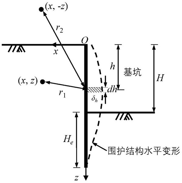
[0064] S2: The horizontal deformation of the foundation pit enclosure structure caused by foundation pit excavation is regarded as the formation loss, and the free field soil level at the side of the foundation pit caused by the horizontal deformation of the foundation pit enclosure structure is obtained by integrating along the depth direction by the source-sink method displacement u ( x , z ) and the vertical displacement s ( x , z );

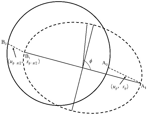
[0065] S3: Extract the horizontal displacement at each point on the tunnel circumference through the obtained horizontal displacement field and vertical displacement field of the free field soil on the side of the foundation pit u ϕ and ver...

Embodiment 2

[0110] Figure 1-6 A method for determining the lateral deformation and internal force of a shield tunnel caused by the excavation of the side foundation pit is shown, which can obtain the displacement of the free-field soil beside the foundation pit after determining the deformation information of the foundation pit enclosure, and establish a method that can consider Modeling of tunnel longitudinal joints to determine tunnel deformations and internal forces.

[0111] The present invention is achieved through the following technical solutions, comprising the following steps:

[0112] The first step is to determine the design parameters and geological condition information of foundation pit and tunnel.

[0113] The design parameters of the foundation pit include: the excavation depth of the foundation pit, the embedding depth of the enclosure structure and the horizontal deformation distribution of the enclosure structure of the foundation pit.

[0114] The tunnel design para...

Embodiment 3

[0147] The first step is to determine the design parameters and geological condition information of foundation pit and tunnel.

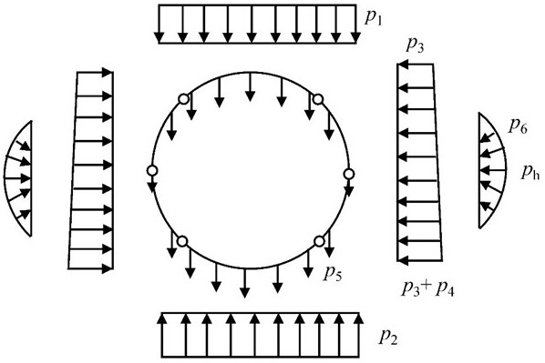
[0148] The soil, tunnel and foundation pit parameters selected in this case are shown in Table 1. In this case, it is assumed that the deformation of the enclosure structure of the foundation pit is a parabolic mode, and the deformation of the enclosure structure has the following expression:

[0149] Formula (14)

[0150] in, h 0 Indicates the maximum deformation of the envelope δ max the depth of burial, δ max = A + B . Take in the case h 0 =15m, A =3, B =33, C =8, the deformation diagram is as follows image 3 shown.

[0151] Table 1 Parameters of soil, tunnel and foundation pit

[0152]

[0153] The second step is to determine the free-field soil displacement on the side of the foundation pit. According to formulas 1 and 2, the soil deformation at any position on the side of the foundation pit can be determined, Figure ...


PUM


Abstract

The invention relates to a method for determining the lateral deformation and internal force of a shield tunnel caused by excavation of a side foundation pit, which specifically includes the following steps: S1: determining the design parameters and geological condition information of the foundation pit and tunnel; S2: obtaining through the source-sink method The horizontal displacement and vertical displacement of the free field soil on the side of the foundation pit caused by the horizontal deformation of the foundation pit enclosure structure; S3: extract the horizontal displacement and vertical displacement at each point on the tunnel circumference, and calculate the convergence at different positions of the tunnel, Determine the maximum convergence and its position; S4: Obtain the pressure distribution pattern around the tunnel; S5: Obtain the load variation ∆p3 of the segment structure, and then obtain the lateral deformation and corresponding internal force of the shield tunnel. The invention can better reflect the deformation law of the shield tunnel caused by the excavation of the side foundation pit, so as to more accurately evaluate the safety state of the shield tunnel under the disturbance of the excavation of the foundation pit.

Description

technical field [0001] The invention relates to a method in the technical field of construction engineering, in particular to a method for determining the cross-sectional deformation and internal force of a shield tunnel caused by excavation of a side foundation pit. Background technique [0002] As the main artery of modern urban underground transportation, the safety of urban subway is directly related to the safety of passengers. In recent years, with the continuous advancement of the urbanization process, the construction of underground spaces in large and medium-sized cities in my country has gradually shown the characteristics and trends of "deep, large, close, and miscellaneous", and will inevitably be carried out around the existing subways. Underground space development. The subway shield tunnel is spliced ​​by prefabricated segments, and the segments are connected by bolts. The overall rigidity of the structure is weak, and the resistance to deformation is poor. D...

Claims


Application Information

Patent Timeline
IPC IPC(8): G06F30/13G06F30/17G06F30/20G06F119/14
CPCG06F30/13G06F30/17G06F30/20G06F2119/14
Inventor 陈仁朋程红战吴怀娜刘源孟凡衍康馨张超杨微
Owner HUNAN UNIV
Why Eureka
Try Eureka