Point cloud labeling method and labeling equipment

A point cloud and point cloud density technology, applied in the field of unmanned driving and automatic driving, can solve the problems of difficult labeling, increasing the difficulty of labeling, insufficient point cloud information of the target object, etc., and achieve the effect of extending the labeling area and reducing the difficulty of labeling

Active Publication Date: 2021-04-27
NEOLIX TECH CO LTD
View PDF15 Cites 0 Cited by
  • Summary
  • Abstract
  • Description
  • Claims
  • Application Information

AI Technical Summary

Problems solved by technology

[0003] At present, the point cloud frames collected for the surrounding environment during the driving of unmanned vehicles are all black and white images, in which the background is black and the point cloud is white, that is, the point cloud frames are images without color information, which would have cost a lot of In terms of manual labeling of time and labor costs, it undoubtedly increases the difficulty of labeling
In particular, within a point cloud frame, objects at different locations correspond to point clouds with different degrees of sparseness, and objects farther away from the unmanned vehicle correspond to sparser point clouds. Therefore, objects farther away from the unmanned vehicle Objects will be difficult to be labeled due to insufficient point cloud information

Method used


Image

  • Point cloud labeling method and labeling equipment
  • Point cloud labeling method and labeling equipment
  • Point cloud labeling method and labeling equipment

Examples


Embodiment 1

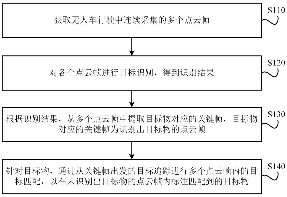
[0057] image 3 Shown is the flow chart of the point cloud labeling method. refer to image 3 , the labeling methods include:

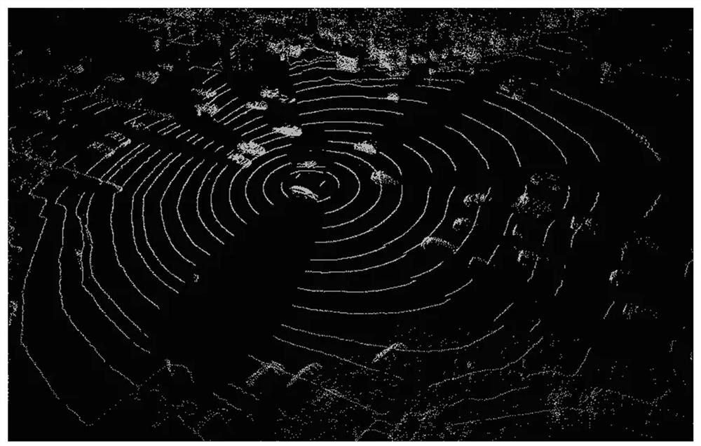
[0058] Step S110, acquiring a plurality of point cloud frames continuously collected during driving of the unmanned vehicle.

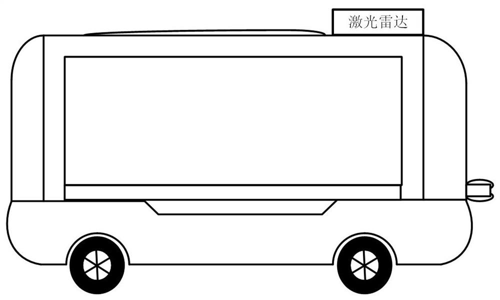
[0059] It should be noted that here, multiple point cloud frames are continuously collected through the laser radar installed on the unmanned vehicle, assuming that the multiple point cloud frames are sorted by the acquisition time as P 1 , P 2 ,...,P n , then multiple point cloud frames P 1 , P 2 ,...,P n There is no point cloud frame in which the position of the target object jumps, that is, the point cloud frame P i is the point cloud frame P i-1 with the point cloud frame P i+1 The transition between point cloud frames, the target object from the point cloud frame P i-1 The position shown passes through the point cloud frame P i Arriving at the point cloud frame P at the position shown i+1 location shown.

[...

Embodiment 2

[0073] The point cloud labeling method provided in this embodiment basically adopts the same process as that in the first embodiment above, so it will not be repeated here.

[0074] The difference is: refer to Figure 4 , step S130, according to the recognition result, extract key frames corresponding to the target object from multiple point cloud frames, including:

[0075] Step S131a, according to the recognition result, determine each point cloud frame in which the target is recognized among the multiple point cloud frames as a candidate frame, and obtain multiple candidate frames;

[0076] Step S132a, obtain the separation distance between the target object and the unmanned vehicle in each candidate frame, and obtain multiple separation distances;

[0077] Step S133a, determining the candidate frame corresponding to the minimum value among the plurality of separation distances as the key frame.

[0078] It should be emphasized that there is a one-to-one correspondence be...

Embodiment 3

[0082] The point cloud labeling method provided in this embodiment basically adopts the same process as that in the first embodiment above, so it will not be repeated here.

[0083] The difference is: refer to Figure 5 , step S130, according to the recognition result, extract key frames corresponding to the target object from multiple point cloud frames, including:

[0084] Step S131a, according to the recognition result, determine each point cloud frame in which the target is recognized among the multiple point cloud frames as a candidate frame, and obtain multiple candidate frames;

[0085] Step S132b, obtaining the interval duration between each candidate frame and the point cloud frame of the unrecognized object in acquisition time, and obtaining multiple interval durations;

[0086] In step S133b, the candidate frame corresponding to the minimum value among the plurality of interval durations is determined as a key frame.

[0087] It should be emphasized that there is ...


PUM


Abstract

The present invention provides a point cloud labeling method and labeling equipment, which relate to the technical field of unmanned driving and automatic driving. frame for target recognition to obtain the recognition result; according to the recognition result, extract the key frame corresponding to the target object from multiple point cloud frames, and the key frame corresponding to the target object is the point cloud frame that recognizes the target object; for the target object, by The target tracking from the key frame performs target matching in multiple point cloud frames, so as to mark the matched target objects in the point cloud frames where no target objects are recognized. The invention can reduce the difficulty of labeling and extend the labeling area.

Description

technical field [0001] The invention relates to the technical field of unmanned driving and automatic driving, and in particular to a point cloud labeling method and labeling equipment. Background technique [0002] For unmanned vehicles, identifying surrounding targets is an essential function. At this stage, this function is implemented based on a deep learning model, and the deep learning model requires point cloud data associated with target information to participate in training before it can be generated. , therefore, it is of great significance to label the target object information on the point cloud data. [0003] At present, the point cloud frames collected for the surrounding environment during the driving of unmanned vehicles are all black and white images, in which the background is black and the point cloud is white, that is, the point cloud frames are images without color information, which would have cost a lot of In terms of manual labeling of time and labo...

Claims


Application Information

Patent Timeline
Patent Type & Authority Patents(China)
IPC IPC(8): G06K9/00G06K9/62
CPCG06V20/46G06V20/56G06F18/22
Inventor 王伟宝
Owner NEOLIX TECH CO LTD
Why Eureka
Try Eureka