Industrial steel ring forming equipment
A forming equipment and an industrial technology, applied in the field of industrial steel ring forming equipment, can solve problems such as being easily injured, and achieve the effect of improving work efficiency
- Summary
- Abstract
- Description
- Claims
- Application Information
AI Technical Summary
Problems solved by technology
Method used
Image

Examples
Embodiment 1
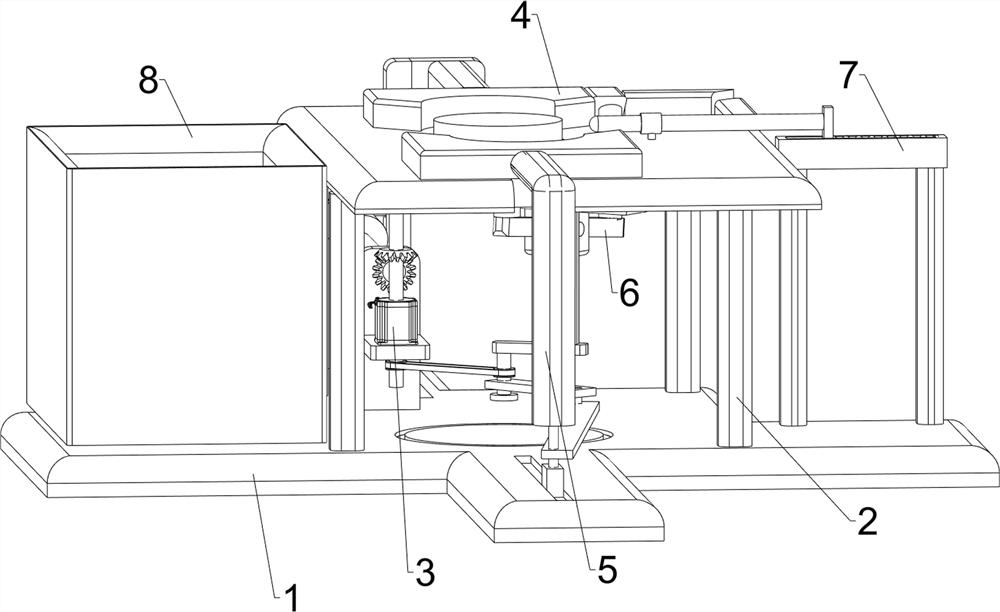
[0053] A kind of industrial steel ring forming equipment, such as figure 1 As shown, it includes a bottom plate 1, a support platform 2, a biaxial motor 3, an advance extrusion mechanism 4, a rear extrusion mechanism 5, and a stopper mechanism 6. The support platform 2 is provided on the middle side of the top of the bottom plate 1, and There is a leading extruding mechanism 4, which is connected with the support table 2, and a biaxial motor 3 is installed on the leading extruding mechanism 4, and a rear extruding mechanism is arranged on the bottom plate 1, the supporting table 2 and the output shaft of the biaxial motor 3. The pressing mechanism 5 is provided with a stopper mechanism 6 on the support platform 2, and the stopper mechanism 6 is connected with the preceding extrusion mechanism 4.
[0054] When forming the steel ring, people first place the steel bar on the support frame between the leading extrusion mechanism 4 and the stopper mechanism 6, and then start the bi...
Embodiment 2
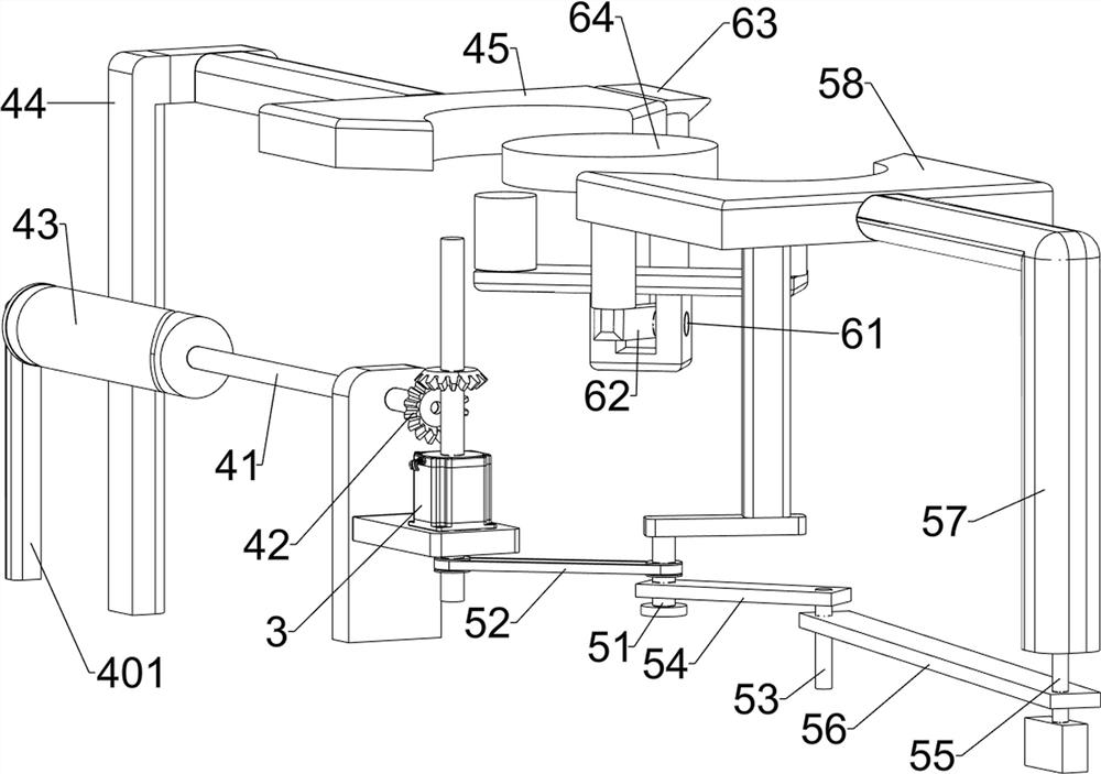
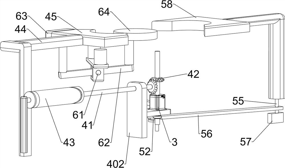
[0056] On the basis of Example 1, such as figure 2 and image 3As shown, the leading extrusion mechanism 4 includes a first support frame 401, a second support frame 402, a first rotating shaft 41, a bevel gear set 42, a space cam 43, a first slider 44 and a leading extrusion block 45, and the bottom plate 1 The top rear side is provided with a first support frame 401 and a second support frame 402, and the second support frame 402 is positioned at the front of the first support frame 401, and a biaxial motor 3 is installed on the front of the second support frame 402, and the second support frame 402 A first rotating shaft 41 is provided in rotation with the first supporting frame 401 top, and a bevel gear set 42 is provided on the output shaft of the first rotating shaft 41 front and the biaxial motor 3 top, and the first rotating shaft 41 rear portion is provided with a space Cam 43, bottom plate 1 top rear side sliding type is provided with first slide block 44, and firs...
Embodiment 3
[0063] On the basis of Example 2, such as figure 1 and Figure 4 As shown, it also includes a pushing mechanism 7 and a holding box 8, the supporting platform 2 is provided with a pushing mechanism 7, the pushing mechanism 7 is connected with the first wedge block 63, and the left side of the bottom plate 1 is provided with a holding box 8 .
[0064] During the forming process of the steel ring, the first wedge-shaped block 63 moves back and forth to drive the pushing mechanism 7 to move left and right, and then continuously pushes the formed steel ring to the holding box 8 to be collected in time.
[0065] Pushing mechanism 7 comprises second wedge-shaped block 71, the 3rd wedge-shaped block 72, push rod 73 and spring 74, and support table 2 top rear side sliding type is provided with second wedge-shaped block 71, and second wedge-shaped block 71 and first wedge-shaped block Block 63 is connected, and the sliding type of support platform 2 right is provided with push rod 73...
PUM
 Abstract
Description
Claims
Application Information
 - R&D
- Intellectual Property
- Life Sciences
- Materials
- Tech Scout
- Unparalleled Data Quality
- Higher Quality Content
- 60% Fewer Hallucinations
Browse by: Latest US Patents, China's latest patents, Technical Efficacy Thesaurus, Application Domain, Technology Topic, Popular Technical Reports.
© 2025 PatSnap. All rights reserved.Legal|Privacy policy|Modern Slavery Act Transparency Statement|Sitemap|About US| Contact US: help@patsnap.com