Raw blank forming equipment for forming powder metallurgy nut

A technology of powder metallurgy and forming equipment, applied in the field of original blank forming equipment for powder metallurgy nut forming, can solve the problems of low work efficiency, time-consuming operation, high labor cost, and achieve the effect of saving labor and reducing waste

Pending Publication Date: 2022-05-06
欧阳宗良
View PDF1 Cites 0 Cited by
  • Summary
  • Abstract
  • Description
  • Claims
  • Application Information

AI Technical Summary

Problems solved by technology

[0005] In order to overcome the shortcomings of low working efficiency, high labor cost and time-consuming operation of the existing molding equipment, the technical problem to be solved is: to provide a powder metallurgy nut molding blank that can automatically control material, automatically collect and automatically unload. molding equipment

Method used


Image

  • Raw blank forming equipment for forming powder metallurgy nut
  • Raw blank forming equipment for forming powder metallurgy nut
  • Raw blank forming equipment for forming powder metallurgy nut

Examples


Embodiment 1

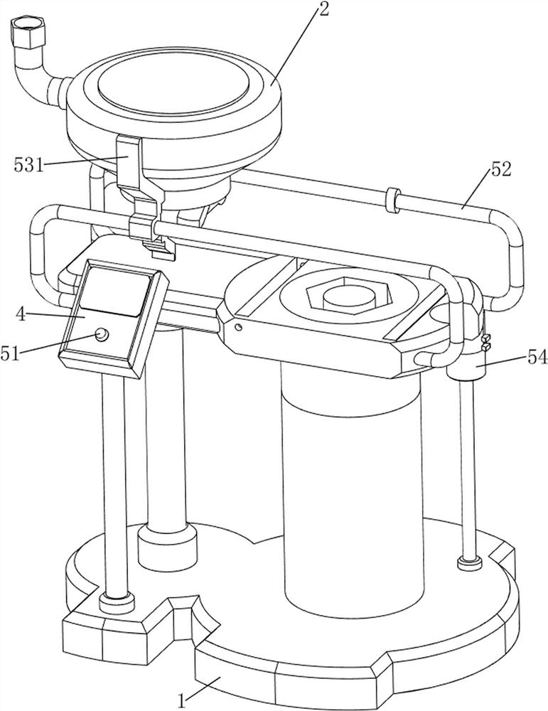
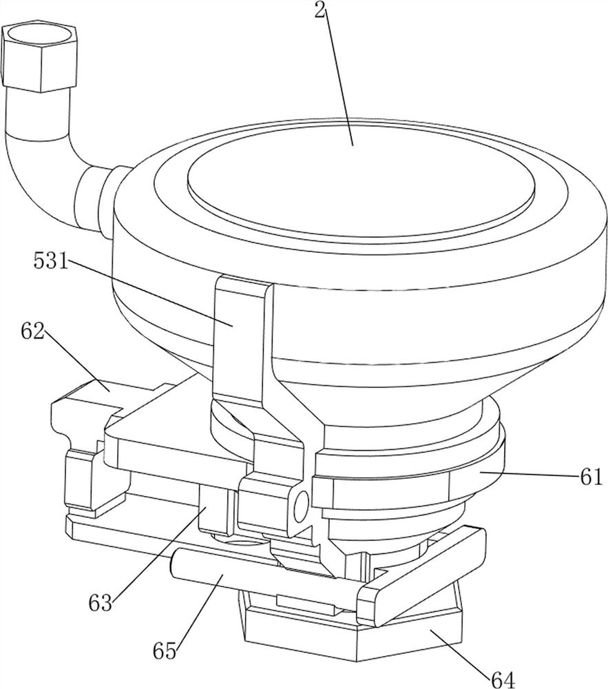
[0037] A kind of blank forming equipment for powder metallurgy nut forming, such as figure 1 , figure 2 , image 3 , Figure 4 , Figure 5 , Figure 6 , Figure 7 , Figure 8 , Figure 9 , Figure 10 , Figure 11 , Figure 14 and Figure 15As shown, it includes a main frame 1, a material box 2, a briquetting block 3, a control box 4, a feeding mechanism 5, a quantitative mechanism 6, a compression mechanism 7 and an extrusion mechanism 8. The main frame 1 is provided with a feeding mechanism 5, and the feeding mechanism 5 is provided with a material box 2, and a control box 4 is provided on the left front side of the top side of the main frame 1. The control box 4 is connected with the feeding mechanism 5. A switching power supply, a control module and a power supply module are installed in the control box 4. The switching power supply is a powder Metallurgical nut forming is powered by the original blank forming equipment. The output end of the switching power sup...

Embodiment 2

[0048] On the basis of Example 1, such as figure 1 , figure 2 , Figure 12 , Figure 13 , Figure 14 and Figure 15 As shown, a blanking mechanism 9 is also included, and the blanking mechanism 9 includes a geared motor 91, a screw 92, a movable block 93, a first slideway 94 and a second slideway 95, and a geared motor is installed on the upper part of the front side of the main body frame 1. 91, the geared motor 91 is connected to the control module through the forward and reverse module of the DC motor, and the inner side of the upper part of the main frame 1 is rotated with a screw 92, which is connected to the output shaft of the geared motor 91, and the screw 92 is screwed with a movable block 93 , the movable block 93 is slidably connected with the main frame 1, the upper right part of the front part of the main frame 1 is provided with a first slideway 94, the upper side of the main frame 1 is provided with a second slideway 95, and the second slideway 95 is connec...


PUM


Abstract

The invention relates to forming equipment, in particular to original blank forming equipment for forming a powder metallurgy nut. The invention provides the protoblank forming equipment for forming the powder metallurgy nut, and the protoblank forming equipment can automatically control materials, automatically collect and automatically unload the materials. A raw blank forming device for powder metallurgy nut forming comprises a main body frame, a material box, a pressing block, a control box, a feeding mechanism, a quantifying mechanism, a compressing mechanism and an extruding mechanism, the feeding mechanism is arranged on the main body frame, the material box is arranged on the feeding mechanism, the control box is arranged on the main body frame, and the control box is connected with the feeding mechanism. A switching power supply, a control module and a power supply module are installed in the control box, and the switching power supply supplies power to the protoblank forming equipment for powder metallurgy nut forming. By arranging the feeding mechanism and the quantifying mechanism, the feeding mechanism operates to drive the quantifying mechanism to operate, so that raw materials intermittently flow downwards, and the effect of automatic material control is achieved.

Description

technical field [0001] The invention relates to a forming device, in particular to a blank forming device for powder metallurgy nut forming. Background technique [0002] Powder metallurgy is a process technology for producing metal powder or using metal powder as raw material, forming and sintering to manufacture metal materials, composite materials and various types of products. Powder metallurgy machines are mainly suitable for pressing and forming various powder materials. However, traditional The efficiency of powder metallurgy machining is relatively low. It is necessary to remove the molded parts when the press stops, and then add raw materials for the next molding process, which is a waste of time and the effect of use is not good. In addition, the traditional molding equipment is processed Finally, it is necessary to manually collect the formed parts, which in turn requires more labor costs. [0003] Patent application CN209632121U, the publication date is 2019.11....

Claims


Application Information

Patent Timeline
Patent Type & Authority Applications(China)
IPC IPC(8): B22F3/03B22F5/06
CPCB22F3/03B22F5/06
Inventor 欧阳宗良
Owner 欧阳宗良
Why Eureka
Try Eureka